
Self-balancing cantilever construction method of long-span steel truss arch bridge and limit bearing of main pier

A technology of steel truss arch bridges and limit bearings, applied in bridges, bridge parts, bridge construction, etc., can solve problems such as blocking the smooth hoisting of bridge deck components, expensive waterway maintenance and management costs, and compressed navigation headroom, etc., to achieve saving Direct engineering costs and waterway maintenance costs, high economy and practicality, and high safety effects

Active Publication Date: 2016-03-02
CHINA RAILWAY SIYUAN SURVEY & DESIGN GRP
View PDF6 Cites 0 Cited by
  • Summary
  • Abstract
  • Description
  • Claims
  • Application Information

AI Technical Summary

Problems solved by technology

[0003] In order to avoid overly complicated structures and minimize the impact of temporary tie rods on the installation of bridge deck components, temporary tie rods are generally located at a node below the bridge deck. The hoisting will affect the construction progress; at the same time, the temporary tie rods located below the bridge deck greatly reduce the navigation clearance height, which requires expensive waterway maintenance and management costs during the construction period, and even affects the bridge plan at bridge sites with high waterway level requirements. implementation; moreover, temporary anchoring measures need to be added to the temporary tie rods, resulting in a complex structure and waste of materials; as the construction progresses, the temporary tie rods need to be stretched multiple times at high altitudes, making construction control difficult

Method used


Image

  • Self-balancing cantilever construction method of long-span steel truss arch bridge and limit bearing of main pier
  • Self-balancing cantilever construction method of long-span steel truss arch bridge and limit bearing of main pier
  • Self-balancing cantilever construction method of long-span steel truss arch bridge and limit bearing of main pier

Examples


Embodiment Construction

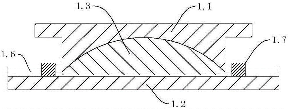
[0020] like figure 1 and image 3 As shown, the limit support of the main pier includes an upper support plate 1.1, a lower support plate 1.2, a spherical crown 1.3 is provided between the upper support plate 1.1 and the lower support plate 1.2, and the upper support plate 1.1 and the lower support plate 1.2 The spherical cap 1.3 is rotationally connected; the spherical cap 1.3 is slidingly connected to the lower support plate 1.2; along the sliding direction of the spherical crown 1.3, the lower support plate 1.2 is provided with a detachable first block 1.4 and the second stopper 1.5, the first stopper 1.4 and the second stopper 1.5 are respectively located on the opposite surface of the lower bearing plate 1.2, the spherical cap 1.3 and the upper bearing plate 1.1 can be positioned at the first stopper 1.4 and the second stopper 1.5; between the first stopper 1.4 and the upper bearing plate 1.5, there are a plurality of detachable adjustment pads 1.6. In order to prevent ...


PUM


Abstract

The invention discloses a self-balancing cantilevering construction method for a large-span steel truss arch bridge. On the basis of additionally arranging temporary tie bars on traditional buckle and back stays, the temporary tie bars are omitted, and main pier limiting supports with horizontally adjustable supporting points are adopted to replace the traditional temporary tie bars for bearing the horizontal thrust applied by an arch ring during construction. A buckle and back stay system is not disassembled when a bridge deck system is assembled after closure of arch ribs so that the horizontal thrust of the supports can be reduced. By adjusting the horizontal displacement of the main pier limiting supports, the functions of the temporary tie bars are achieved, and control over the stress displacement of the bridge during the construction and stress-free closure of rigid tie bars are achieved. After the closure of the rigid tie bars, the buckle and back stay system is disassembled. Finally, the main pier limiting supports are disassembled step by step, and the rigid tie bars are stressed, and therefore system conversion is completed.

Description

technical field [0001] The invention belongs to a construction method of a steel truss arch bridge, in particular to a self-balancing suspension construction method of a steel truss arch bridge without temporary tie rods, and a space-limiting support for a main pier used in the method. Background technique [0002] For long-span steel truss arch bridges, after the arch ribs are closed and before the steel ties on the bridge deck are closed, temporary ties need to be installed to form a tie-arch system in advance, and the temporary ties are stretched multiple times to balance the horizontal thrust of the arch feet to achieve Control of stress-displacement of bridges during construction and stress-free closure of rigid tie rods. [0003] In order to avoid overly complicated structures and minimize the impact of temporary tie rods on the installation of bridge deck components, temporary tie rods are generally located at a node below the bridge deck. The hoisting will affect th...

Claims


Application Information

Patent Timeline
Patent Type & Authority Patents(China)
IPC IPC(8): E01D21/10E01D19/04
Inventor 罗世东王新国曾敏瞿国钊任巍峰夏正春
Owner CHINA RAILWAY SIYUAN SURVEY & DESIGN GRP
Learn More