
Vertical shaft cement discharging system with secondary stirring device

A secondary mixing and wellbore technology, which is applied in shaft lining, shaft equipment, mining equipment, etc., can solve the problems of prolonging the time for ash removal, failure to ensure continuous pouring of concrete, waste of manpower, etc., to prevent concrete segregation, ensure concrete quality, The effect of improving work efficiency

Active Publication Date: 2014-07-23
CHINA COAL FIRST CONSTR
View PDF7 Cites 4 Cited by
  • Summary
  • Abstract
  • Description
  • Claims
  • Application Information

AI Technical Summary

Problems solved by technology

The disadvantage is that it is difficult to ensure that the concrete does not segregate
2. Use the bottom-unloading bucket to cooperate with the "slide type" chute to lower the ash. Through use, it is found that although this design can meet the requirements for ash lowering, it also has many shortcomings: (1) When using the bottom-unloading bucket to lower the ash, it is necessary to use the main, The sub-lift is lowered and lifted, and it is necessary to arrange 4 to 6 people at the wellhead and the hanging pan to push, hold and stabilize the tank, which is a waste of manpower; If a failure occurs, it will lead to the interruption of ash loading or the prolongation of the ash loading time, so that the continuous pouring of concrete cannot be guaranteed, resulting in a waste of manpower and resources and prone to safety accidents
(3) The "slide type" chute is placed on the hanging pan, occupying limited space on the hanging pan

Method used


Image

  • Vertical shaft cement discharging system with secondary stirring device
  • Vertical shaft cement discharging system with secondary stirring device

Examples


Embodiment Construction

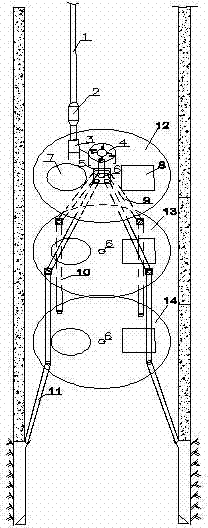
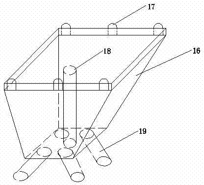
[0013] figure 1 Among them, the ash lowering system of the vertical shaft shaft equipped with the secondary stirring device is mainly composed of the main ash chute pipe 1, the buffer 2, the ash hopper 3, the secondary stirring device 4, the ash separator 5, the center line mouth 6, and the main hoisting horn 7. Auxiliary lifting bell mouth 8, slide chute 9, short ash chute 10, rubber hose 11, hanging pan I12, hanging pan II13 and hanging pan III14, and its hanging pan I12, hanging pan II13 and hanging pan III14 The main hoist bell mouth 7 and the auxiliary hoist bell mouth 8 are arranged on the left and right respectively, and the center line mouth 6 is arranged in the middle. The ash separator 5 is arranged on the upper part of the hanging pan I12, and the middle line pipe 18 in the middle of the ash separator 5 is connected with the center line on the hanging pan I12. The outlet 6 is on a central line, and the four ash outlets 19 provided at the lower part of the ash separ...


PUM


Abstract

The invention discloses a vertical shaft cement discharging system with a secondary stirring device. The vertical shaft cement discharging system is mainly formed by a main cement sliding pipe, a buffer, a cement hopper, the secondary stirring device, a cement dividing device, center line openings, main lifting horn mouths, auxiliary lifting horn mouths, slide type sliding grooves, a short cement sliding pipe, a rubber soft pipe, a first hanging disc, a second hanging disc and a third hanging disc. The first hanging disc, the second hanging disc and the third hanging disc are respectively provided with the main lifting horn mouths and auxiliary lifting horn mouths in a left-and-right mode, the center line openings are formed in the middles, the cement dividing device is arranged on the upper portion of the first hanging disc, a center line pipe in the middle of the cement dividing device and the center line opening in the first hanging disc are located in the same center line, four cement outlets are formed in the lower portion of the cement dividing device, penetrate through the first hanging disc, and are connected with the four slide type sliding grooves respectively, and the four slide type sliding grooves respectively penetrate through the second hanging disc to be connected with the short cement sliding pipe. By means of the vertical shaft cement discharging system, continuous concrete discharging of a deep vertical shaft is achieved, and meanwhile concrete disintegration is avoided; the concrete quality is accordingly guaranteed, and the working efficiency is improved.

Description

technical field [0001] The invention relates to a mechanical device, in particular to a mechanical device used in a shaft ash lowering system. Background technique [0002] During the construction of the deep shaft, 1. For example, the ash chute is used to lower the high-grade concrete and transport it to the suspension plate through the buffer, and then convey it from the "slide type" chute to the formwork to complete the concrete pouring. The disadvantage is that it is difficult to ensure that the concrete does not segregate. 2. Use the bottom-unloading bucket to cooperate with the "slide type" chute to lower the ash. Through use, it is found that although this design can meet the requirements for ash lowering, it also has many shortcomings: (1) When using the bottom-unloading bucket to lower the ash, it is necessary to use the main, The sub-lift is lowered and lifted, and it is necessary to arrange 4 to 6 people at the wellhead and the hanging pan to push, hold and stabi...

Claims


Application Information

Patent Timeline
Patent Type & Authority Applications(China)
IPC IPC(8): E21D5/04E21D5/12
Inventor 张晓震王强
Owner CHINA COAL FIRST CONSTR
Learn More