Damping noise reduction valve plate for plunger hydraulic pump

A valve plate, hydraulic pump technology, applied in pump components, variable capacity pump components, liquid fuel engines, etc., can solve the problems of valve plate surface damage, cavitation, bubble generation, etc., to achieve good anti-pollution ability and reduce noise. , the effect of eliminating cavitation

Active Publication Date: 2014-07-23
TONGJI UNIV
View PDF6 Cites 13 Cited by
  • Summary
  • Abstract
  • Description
  • Claims
  • Application Information

AI Technical Summary

Problems solved by technology

[0006] 1. In the oil suction waist window of the distribution plate, air bubbles will inevitably be generated due to the negative pressure generated during the oil absorption process, and these bubbles will enter the oil discharge waist window with the plunger cavity;
[0007] 2. In the oil discharge waist window of the valve plate, due to the sudden change of the oil from low pressure to high pressure, the air bubbles will burst under pressure, causing damage to the surface of the valve plate or the cylinder body, that is, cavitation
Although the above structure has improved the noise suppression and flow impact of the flow plate, it cannot completely solve the problem of cavitation wear caused by the rupture of bubbles in the oil suction and discharge transition area of ​​the flow plate.

Method used


Image

  • Damping noise reduction valve plate for plunger hydraulic pump
  • Damping noise reduction valve plate for plunger hydraulic pump
  • Damping noise reduction valve plate for plunger hydraulic pump

Examples


Embodiment 1

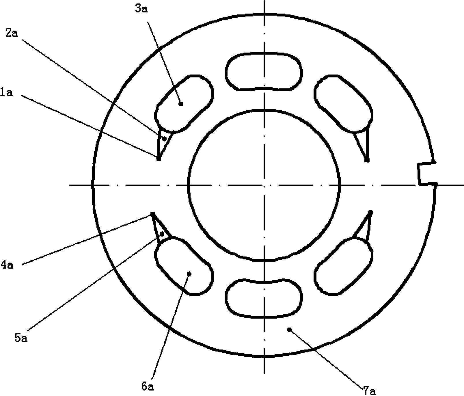
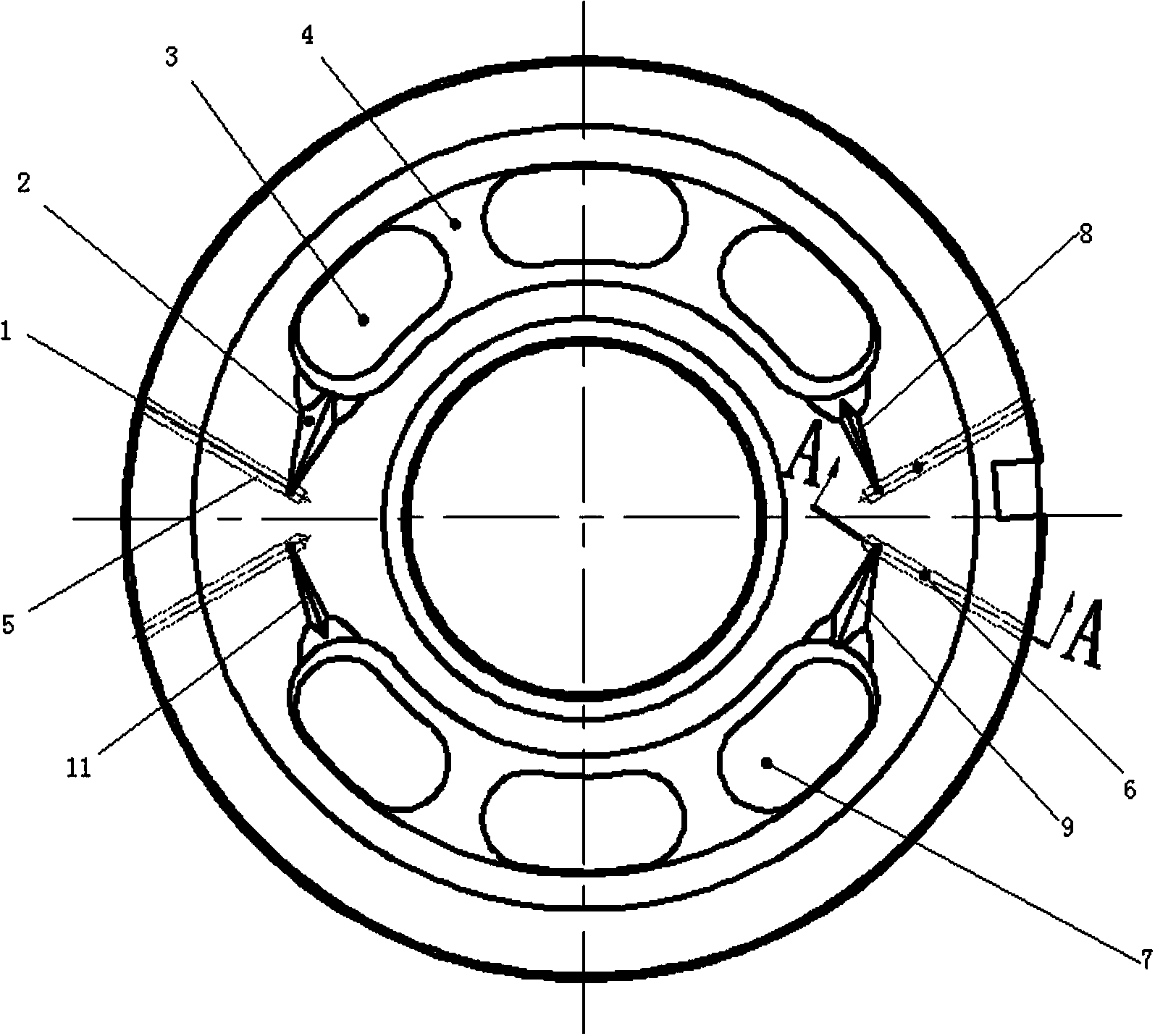
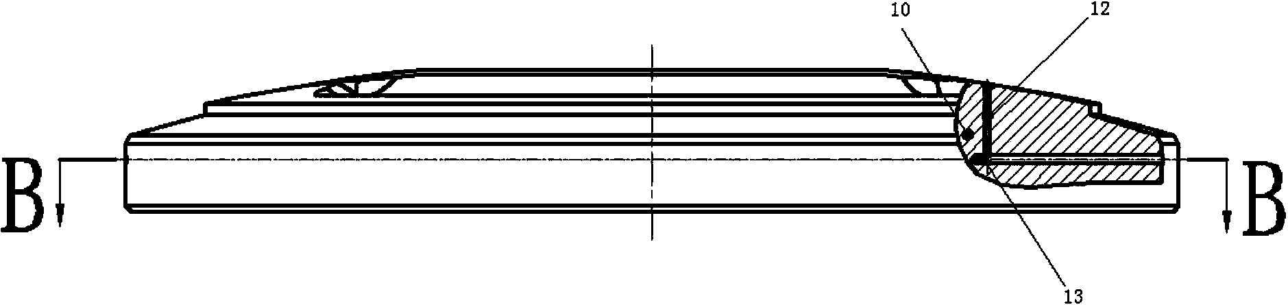
[0030] Such as Figure 2-4As shown, a shock-absorbing and noise-reducing valve plate for a plunger hydraulic pump includes a valve plate body 10, and the valve plate body 10 is provided with a low-pressure oil suction area that is isolated from each other and is symmetrical with respect to the horizontal axis of the valve plate body 10. High-pressure oil discharge area; the low-pressure oil-absorbing area includes an arc-shaped groove, an oil-absorbing waist-shaped window 3 and a reinforcing rib 4 arranged at the bottom of the arc-shaped groove, and the oil-absorbing waist-shaped window 3 is at least one; the described The high-pressure oil discharge area includes an arc groove, an oil discharge waist window 7 and a reinforcing rib arranged at the bottom of the arc groove, the oil discharge waist window 7 is at least one; the two ends of the low pressure oil suction area and Both ends of the high-pressure oil discharge area are provided with a triangular groove connected to it...

Embodiment 2

[0034] In this embodiment, four oil-absorbing waist-shaped windows 3 and four oil-discharging waist-shaped windows 7 are respectively provided. At the same time, the oil passages arranged at the bottom of the four damping holes have a diameter of 0.8 mm in the vertical section and 0.8 mm in diameter of the oil passage in the horizontal section. Diameter is 1.5mm, and all the other are with embodiment 1.

Embodiment 3

[0036] In this embodiment, five oil suction waist windows 3 and five oil discharge waist windows 7 are respectively provided. At the same time, the oil passages arranged at the bottom of the four damping holes have a diameter of 1mm in the vertical section and 1mm in the horizontal section. Be 2mm, all the other are with embodiment 1.


PUM


Abstract

The invention relates to a damping noise reduction valve plate for a plunger hydraulic pump. The damping noise reduction valve plate for the plunger hydraulic pump comprises a valve plate body which is provided with a low pressure oil suction area and a high pressure oil discharging area, wherein the low pressure oil suction area and the high pressure oil discharging area are isolated from each other and are symmetric relative to a horizontal shaft of the valve plate body. The two ends of the low pressure oil suction area and the two ends of the high pressure oil discharging area are respectively communicated with a triangular groove. A damping hole is formed in the bottom of the top end of the triangular groove, an oil channel is formed in the bottom of the damping hole, and the oil channel is communicated with an inner cavity of a pump shell through the cylindrical side face of the valve plate body. The oil channel is composed of a vertical section oil channel and a horizontal section oil channel. Through the arranged oil channel, bubbles generated in the working process and bubbles sucked in can be timely discharged into the cavity of the pump shell, and therefore cavitation, noise and vibration caused by bubble breakage are lowered. The damping noise reduction valve plate for the plunger hydraulic pump obviously improves the cavitation resistance of the plunger pump, and has the advantages of being small in vibration, low in noise, good in working stability and the like.

Description

technical field [0001] The invention belongs to the technical field of hydraulic components of mechanical engineering, and relates to a flow plate, in particular to a shock-absorbing and noise-reducing flow plate for a plunger hydraulic pump. Background technique [0002] The distribution plate is one of the key parts of the plunger pump. It plays the role of communicating the oil inlet and outlet of the plunger pump during the working process of the plunger pump. At the same time, the plunger hole of the cylinder absorbs oil from the distribution plate. The waist window absorbs oil and discharges oil. Waist-shaped window discharges high-pressure oil; it is inevitable that when switching from a high-pressure area to a low-pressure area, the oil will precipitate gas due to a sudden change in pressure, and bubbles will burst near the low-pressure area, resulting in cavitation at the triangular groove of the valve plate. It will cause the flow plate to generate a large number o...

Claims


Application Information

Patent Timeline
Patent Type & Authority Applications(China)
IPC IPC(8): F04B53/00
Inventor 李晶訚耀保王智勇汤何胜
Owner TONGJI UNIV
Why Eureka
Try Eureka