Supercharge Your Innovation With Domain-Expert AI Agents!

Method used for reducing residual impedance effect of voltage transformer and inductive voltage divider primary winding

A technology of inductive voltage divider and voltage transformer, which is applied in the direction of transformer/inductor coil/winding/connection, voltage divider, inductor, etc., can solve problems such as errors, and achieve accurate and efficient transformers and inductive voltage dividers. Reduce the influence of residual impedance, the effect of large influence

Inactive Publication Date: 2014-07-23
上海浦东金盛互感器厂
View PDF5 Cites 7 Cited by
  • Summary
  • Abstract
  • Description
  • Claims
  • Application Information

AI Technical Summary

Problems solved by technology

figure 1 It is a single-stage voltage transformer or inductive voltage divider, because the voltage drop on the residual impedance of the primary winding cannot be coupled to the secondary winding, so a large error is generated

Method used


Image

  • Method used for reducing residual impedance effect of voltage transformer and inductive voltage divider primary winding
  • Method used for reducing residual impedance effect of voltage transformer and inductive voltage divider primary winding
  • Method used for reducing residual impedance effect of voltage transformer and inductive voltage divider primary winding

Examples


Embodiment 1

[0027] Example 1, Figure 8 It is a schematic diagram of the method for reducing the influence of the residual impedance of the primary winding of the voltage transformer and the inductive voltage divider described in the present invention, and uses this example to further analyze the essence of the method.

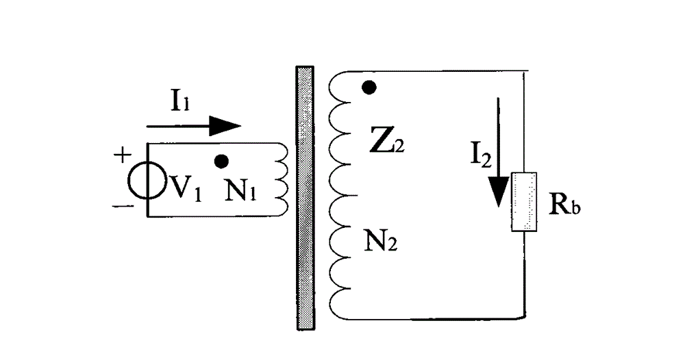
[0028] Let the primary voltage be V 1 , N 1 Winding inductance is Z 1 , the resistance is r 1 , the leakage inductance is l 1 , then the primary winding residual impedance z 1 = r 1 +jωl 1 , current I 1 Flow-through inductive reactance Z 1 The voltage drop across the I 1 Z 1 . Let N 1 , N 2 Between ideal coupling, the voltage I 1 Z 1 will be coupled to winding N 2 , so follower A 1 The input voltage is the primary voltage V 1 coupled with the winding N 2 The difference in the induced voltage, that is, V 1 -I 1 Z 1 , the difference voltage is amplified k times by the inverting amplifier. Amplifier output via DC blocking capacitor C 1 with winding N ...

Embodiment 2

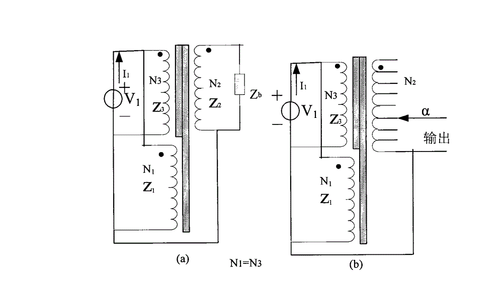
[0030] Embodiment 2, press Figure 7 A double-stage voltage transformer is manufactured with the present invention, the primary voltage is 1000 volts, the secondary voltage is 100 volts, the frequency is 50 Hz, and the load is zero VA.

[0031] Iron core 1 is made of silicon steel Z10 and a strip with a thickness of 0.3mm, the specification is Φ60×180 / 80, and 1000 turns are evenly wound with Φ0.13QZ wire as N 1 , the inductance is 300H, the resistance r 1 =400Ω, approximate residual inductance, then the resistance r 1 The introduced error is -r 1 / Z 1 =j400 / (314×300)=4.246×10 -3 (radian) = 14.6 (minutes). Wind 1000 turns uniformly with Φ0.12QZ wire as N 3 .

[0032] Now stack the iron core 2, the material is nanocrystalline 1k107, the specification is Φ53×187 / 10, use Φ0.13QZ wire to wind 1000 turns evenly on the two iron cores as N 4 , the inductance is 530H, the resistance r 4 =440Ω, approximate residual inductance, then the resistance r 4 The introduced error is -r...


PUM


Abstract

The invention provides a method used for reducing the residual impedance effect of a voltage transformer and inductive voltage divider primary winding, which belongs to the field of measuring test. According to the invention, a compensation voltage is inserted into a voltage transformer and inductive voltage divider primary circuit, so as to offset the voltage drop effect on the residual impedance of the primary winding; the compensation voltage is acquired by amplifying voltage drop which is indirectly taken from the residual impedance; a primary voltage is equal to an inductor added on the primary winding; a voltage on the inductor can be coupled to another winding which is tightly coupled to the primary winding according to turn ratio; another winding acquires the accurate voltage, wherein the residual impedance effect of the voltage is eliminated; and the accuracy of the voltage transformer and the inductive voltage divider can be greatly improved.

Description

technical field [0001] The invention belongs to the field of measurement and testing. The method can reduce the influence of the excitation current on the residual impedance of the primary winding of the voltage transformer and the induction voltage divider, thereby greatly improving the accuracy of the voltage transformer and the induction voltage divider. The invention is especially suitable for manufacturing high-precision Degree of low frequency voltage transformer and low frequency induction voltage divider. Background technique [0002] Potential transformers and inductive voltage dividers are voltage proportional devices, which usually convert a higher voltage into a lower voltage for easy measurement. Because of its high accuracy, reliable operation and long life, it is used in power generation, transmission It is widely used in power distribution, power consumption, instrumentation, automation, relay protection and other fields. [0003] Due to the wide range of a...

Claims


Application Information

Patent Timeline
IPC IPC(8): G01R15/04H01F38/24H01F27/28H01F27/34
Inventor 陆文俊
Owner 上海浦东金盛互感器厂
Features
  • R&D
  • Intellectual Property
  • Life Sciences
  • Materials
  • Tech Scout
  • Unparalleled Data Quality
  • Higher Quality Content
  • 60% Fewer Hallucinations
Learn More