Radiation net fault location method by means of zero mode and aerial mode time difference independent of double-end synchronization and with matching of magnitude of voltages and magnitude of currents

A technology of fault location and current flow, applied in fault location, measurement of electrical variables, measurement of electricity, etc., can solve the problems of high operating cost of the double-ended traveling wave method and difficulty in calibrating the arrival time of the reflected wave head

Active Publication Date: 2014-07-23
KUNMING UNIV OF SCI & TECH
View PDF8 Cites 21 Cited by
  • Summary
  • Abstract
  • Description
  • Claims
  • Application Information

AI Technical Summary

Problems solved by technology

[0004] The technical problem to be solved by the present invention is to provide a method for locating faults in zero- and line-mode time-difference radiation networks using voltage and current coordination that does not rely on double-terminal synchronization, so as to overcome the arrival of reflected wav

Method used


Image

  • Radiation net fault location method by means of zero mode and aerial mode time difference independent of double-end synchronization and with matching of magnitude of voltages and magnitude of currents
  • Radiation net fault location method by means of zero mode and aerial mode time difference independent of double-end synchronization and with matching of magnitude of voltages and magnitude of currents
  • Radiation net fault location method by means of zero mode and aerial mode time difference independent of double-end synchronization and with matching of magnitude of voltages and magnitude of currents

Examples


Embodiment 1

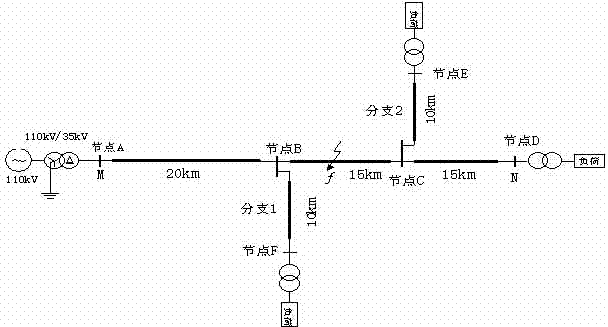
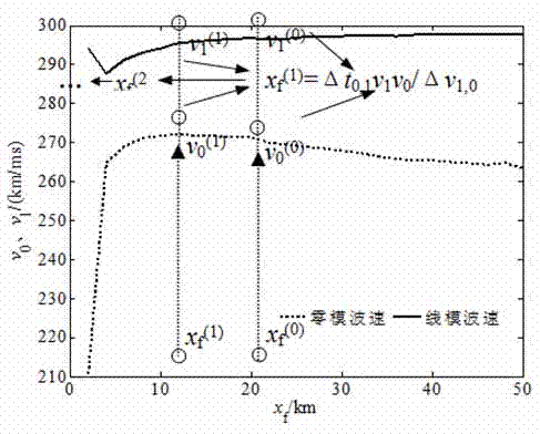
[0031] Example 1: Assuming that a phase A metallic grounding fault occurs on the branch 2 line 40km away from the M terminal, the initial phase angle of the fault is 90°, the simulation sampling frequency is 10MHz, and the wavelet modulus maximum value pairs under the fifth scale are used to measure The line and zero-mode traveling wave components detected at the terminal are calibrated at time, and the M-side line and zero-mode current are as follows: Figure 4 , Figure 5 As shown, N-side line, zero-mode voltage as Figure 6 , Figure 7 shown. The arrival time difference of the M lateral line and zero-mode wave is △ t M = 0.0156ms, the time difference between N-side line and zero-mode wave arrival is △ t N =0.0062ms, select the wave velocity at the midpoint of the feeder as the initial wave velocity iteration value, and use the ranging formula Calculate the initial distance to fault x f (0) , the initial fault distance x f (0) Substituting the line and zero-mo...

Embodiment 2

[0032] Example 2: Assuming that a phase A metallic grounding fault occurs on the main line 25km away from the M terminal, the initial phase angle of the fault is 90°, the fault transition resistance is 300Ω, and the simulation sampling frequency is 10MHz, respectively using the wavelet mode poles under the fifth scale The maximum value is used to calibrate the line and zero-mode traveling wave components detected by the measuring terminal at time, and obtain the M measuring terminal line, zero-mode current traveling wave, N measuring terminal line, zero-mode voltage traveling wave and its modulus maximum value calibration. The arrival time difference between M side and N side line and zero-mode wave is △ t M and △ t N , select the wave velocity at the midpoint of the feeder as the initial wave velocity iterative value, and use the ranging formula Calculate the initial distance to fault x f (0) , the initial fault distance x f (0) Substituting the line and zero-mode i...


PUM


Abstract

The invention provides a radiation net fault location method by means of a zero mode and aerial mode time difference independent of double-end synchronization and with matching of the magnitude of voltages and the magnitude of currents, and belongs to the technical field of power system relay protection. The two sides of a feeder are respectively provided with a traveling wave fault location device, and fault location is carried out according to information on the two sides. After a ground fault of the feeder of a power distribution net occurs, due to sudden changes of the voltage at a fault point, an aerial mode traveling wave component spreading between wires and a zero mode traveling wave component spreading between the wires and the ground are generated. Due to the fact that the spreading speeds of an aerial mode and a zero mode are different, the arrival moment of an aerial mode traveling wave detected by the measurement end and the arrival moment of a zero mode traveling wave detected by the measurement end are different. According to original aerial mode voltage and current traveling wave data and original zero mode voltage and current traveling wave data detected by the measurement end, wave arrival moment calibration is carried out by means of a wavelet modulus maximum value under a fifth dimension, and then the fault position is calculated according to a calculation formula of a ground fault single-end traveling wave fault location method of modulus transmission time differences. Fault location is carried out according to measurement information of the single-end modulus transmission time differences at two sides.

Description

technical field [0001] The invention relates to a method for locating faults in zero- and line-mode time-difference radiation networks using voltage and current coordination without relying on double-terminal synchronization, and belongs to the technical field of electric power system relay protection. Background technique [0002] Fault location after a fault occurs in the power grid can reduce the workload of manual line inspection, shorten the fault repair time, improve the reliability of power supply, reduce the loss of power outage, and find hidden dangers and deal with them as soon as possible to prevent the recurrence of faults. The method of fault location can be divided into fault analysis method and traveling wave method according to the principle of distance measurement. The core of the traveling wave method is to measure the propagation time of the traveling wave between the bus and the fault point to calculate the line fault distance. Traveling wave ranging can...

Claims


Application Information

Patent Timeline
IPC IPC(8): G01R31/08G01R31/02
Inventor 束洪春王瑶韩倩倩
Owner KUNMING UNIV OF SCI & TECH
Why Eureka
Try Eureka