Electrowetting display panel and display device

An electrowetting display and panel technology, applied in optical components, optics, instruments, etc., can solve the problems of poor color electrowetting display display effect, etc., and achieve the effects of bright colors, simplified production process, and high display brightness.

Inactive Publication Date: 2014-07-23
BOE TECH GRP CO LTD
View PDF4 Cites 11 Cited by
  • Summary
  • Abstract
  • Description
  • Claims
  • Application Information

AI Technical Summary

Problems solved by technology

[0008] The present invention provides an electrowetting display panel and a display device, which are used to solve the problem of poor display effect of color electrowetting displays in the prior art

Method used


Image

  • Electrowetting display panel and display device
  • Electrowetting display panel and display device
  • Electrowetting display panel and display device

Examples


Embodiment 1

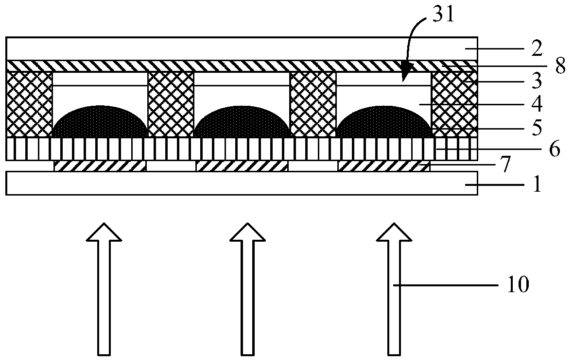
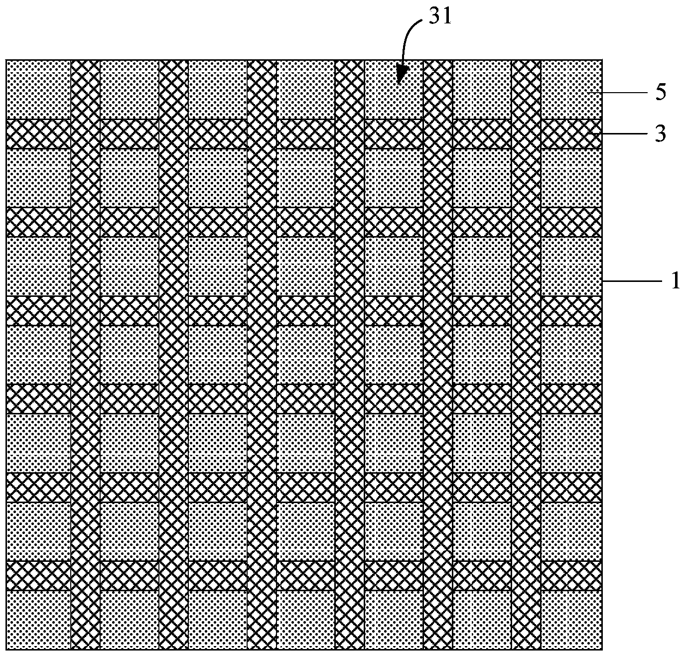
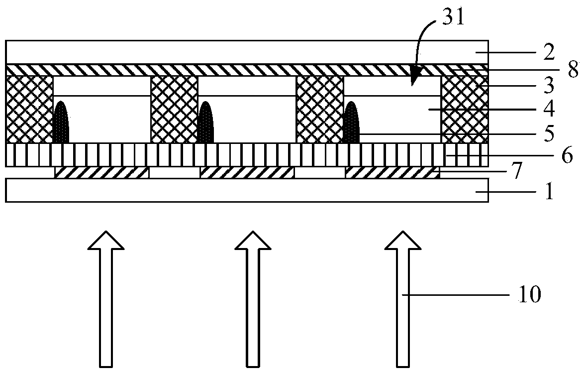
[0024] Combine figure 1 with figure 2 As shown, an embodiment of the present invention provides an electrowetting display panel, which includes a first substrate 1 and a second substrate 2 disposed oppositely, and a plurality of isolation walls between the first substrate 1 and the second substrate 2 3. A plurality of isolation walls 3 are arranged on the first substrate 1 in a lattice shape, and adjacent isolation walls 3 form a plurality of sealed lattice spaces 31 to define sub-pixel units of the electrowetting display panel. Among them, the first substrate 1 and the second substrate 2 are transparent substrates, such as quartz substrates, glass substrates or organic resin substrates.

[0025] The plurality of sealed grid spaces 31 are filled with mutually incompatible quantum dot solution 4 and shading fluid 5, and the shading fluid 5 is located between the quantum dot solution 4 and the first substrate 1 for blocking the back of the first substrate 1 The incident light 10 ...

Embodiment 2

[0038] An embodiment of the present invention also provides a display device, which includes the electrowetting display panel in the first embodiment, and also includes a backlight source that provides light for the electrowetting display panel. Wherein, the backlight source may include a blue, violet or ultraviolet excitation light source.

[0039] By using the excited self-luminescence of the quantum dot solution, the brightness and color saturation of the display device can be improved, and the display effect can be improved. In addition, the mutually incompatible quantum dot solution and the light-shielding solution are filled in the sealed lattice space, and a single-layer electrowetting structure can be used to realize a transmissive color display device, which has a simple structure and a simplified manufacturing process.

[0040] The electrowetting display panel of the present invention includes a first substrate and a second substrate that are opposed to each other. On the...


PUM


Abstract

The invention relates to the technical field of display, and discloses an electrowetting display panel and a display device. The display panel comprises a first substrate and a second substrate which are oppositely arranged, wherein a first transparent electrode and an electric control dielectric layer of electrogenerated hydrophilic shading fluid or hydrophobic shading fluid are formed on the first substrate, a quantum dot solution is arranged between the shading fluid and the second substrate, when voltage is applied to the electric control dielectric layer through the first transparent electrode, shrinkage of the shading fluid is controlled, the quantum dot solution is exposed, light entering from the back side of the first substrate is irradiated to the quantum dot solution, quantum dots are stimulated to give out light automatically, colored display is achieved, high display brightness is achieved, the color is bright, color saturation is good, and the display effect is improved. Meanwhile, a sealed grid-shaped space is filled with the quantum dot solution and the shading fluid which are not compatible with each other, the transmission-type colored display device can be implemented through a single-layer electrowetting structure, the structure is simple, and the manufacturing technology is simplified.

Description

Technical field [0001] The present invention relates to the field of display technology, in particular to an electrowetting display panel and a display device. Background technique [0002] The principle of Electrowetting (Electrowetting) display technology is to use the phenomenon of electrowetting or electrocapillary (Electrocapillary) to change the free surface energy (Free Surface Energy) of the fluid by controlling the fluid under the action of an electric field to change the distribution area of ​​the fluid. And then control the change of pixels to achieve specific display effects. Electrowetting display technology has attracted much attention because of its low power consumption, wide viewing angle and high response speed. [0003] At present, color electrowetting displays are the focus of research and development. There are mainly three types of color electrowetting displays in the prior art, namely: [0004] The first is the pre-filter method. A color filter is arranged o...

Claims


Application Information

Patent Timeline
Patent Type & Authority Applications(China)
IPC IPC(8): G02B26/00
Inventor 李琳唐琛常珊
Owner BOE TECH GRP CO LTD
Why Eureka
Try Eureka