Touch control structure, touch screen and touch display device
A touch screen and touch technology, which is applied in the fields of instruments, calculations, electrical digital data processing, etc., can solve the problems that the drive chip is difficult to scan the second connecting line, and the difficulty of panel wiring is increased, so as to achieve convenient design and touch resolution The effect of increasing the rate and reducing the number
- Summary
- Abstract
- Description
- Claims
- Application Information
AI Technical Summary
Problems solved by technology
Method used
Image
Examples
Embodiment 1
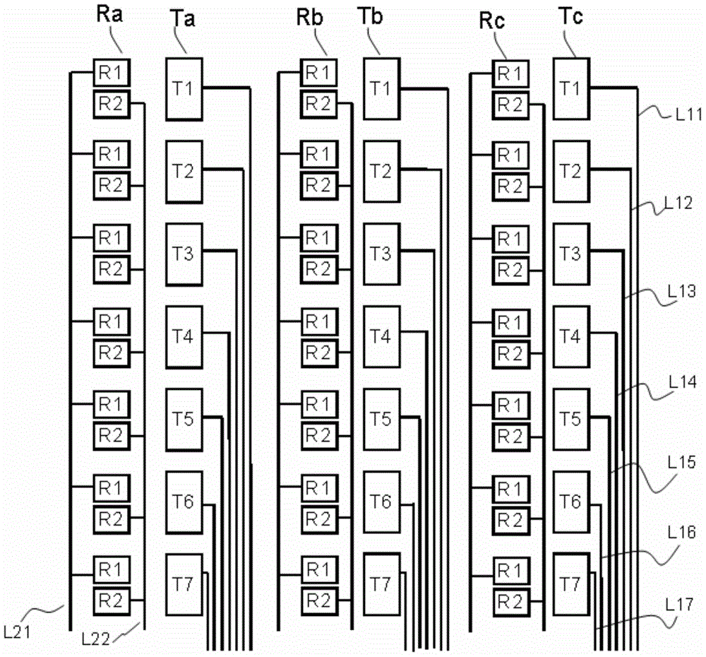
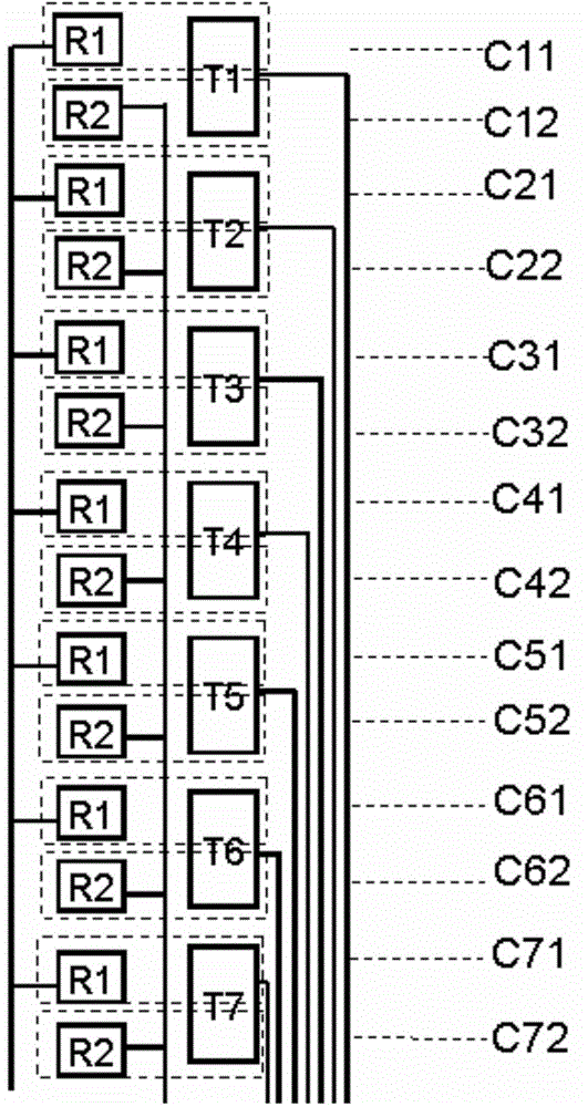
[0024] Please refer to figure 2 and image 3 , figure 2 The touch structure provided by Embodiment 1 of the present invention, image 3 It is a schematic diagram of a row of driving electrodes and a row of sensing electrodes. As shown in the figure, the touch control structure provided by Embodiment 1 of the present invention includes multiple rows of driving electrodes Ta, Tb, Tc, multiple rows of sensing electrodes Ra, Rb, Rc, and the multiple rows of driving electrodes Ta, Tb, Tc and multiple rows The row sensing electrodes Ra, Rb, and Rc are arranged at intervals.
[0025] Each row of driving electrodes includes a plurality of driving electrodes T1, T2, ... T7, and each row of sensing electrodes includes a plurality of sensing electrodes, for example, a row of sensing electrodes includes 7 sensing electrodes R1 and 7 sensing electrodes R2.
[0026] It also includes a plurality of driving signal pins and a plurality of sensing signal pins. The plurality of driving el...
Embodiment 2
[0039] Please refer to Figure 5 , Figure 5 It is a schematic diagram of the touch screen provided by Embodiment 2 of the present invention. The touch screen includes a substrate 200 and a touch structure on the substrate 200 .
[0040] The touch control structure includes multi-row driving electrodes Ta, Tb, Tc, multi-row sensing electrodes Ra, Rb, Rc, and the multi-row driving electrodes Ta, Tb, Tc and multi-row combined sensing electrodes Ra, Rb, Rc are interval set. Each row of driving electrodes includes multiple driving electrodes T1, T2, ... T7, and each row of combined sensing electrodes includes multiple combined sensing electrodes. For example, a row of combined sensing electrodes includes 4 combined sensing electrodes R11, R12, R21, R22, etc. .
[0041] It also includes a plurality of driving signal pins and a plurality of sensing signal pins. The plurality of driving electrodes T1, T2, ... T7 in each row of driving electrodes are electrically connected to the...
Embodiment 3
[0050] Please refer to Figure 6 , Figure 6 It is a schematic diagram of the touch structure provided by Embodiment 3 of the present invention. The touch control structure provided in the third embodiment includes the touch control structure provided in the first embodiment of the present invention including multiple rows of driving electrodes and multiple rows of sensing electrodes, and the multiple rows of driving electrodes and multiple rows of sensing electrodes are arranged at intervals. Embodiment 3 shows a row of driving electrodes and a row of sensing electrodes.
[0051] Each row of driving electrodes includes a plurality of driving electrodes T1, T2, T3, and T4, and each group of sensing electrodes in each row of sensing electrodes includes sensing electrodes and combination sensing electrodes, specifically, each group of sensing electrodes includes sensing electrodes R2 and combined sensing electrodes. Sensing electrodes R1, R3.
[0052] It also includes a plura...
PUM
 Abstract
Description
Claims
Application Information
 - R&D
- Intellectual Property
- Life Sciences
- Materials
- Tech Scout
- Unparalleled Data Quality
- Higher Quality Content
- 60% Fewer Hallucinations
Browse by: Latest US Patents, China's latest patents, Technical Efficacy Thesaurus, Application Domain, Technology Topic, Popular Technical Reports.
© 2025 PatSnap. All rights reserved.Legal|Privacy policy|Modern Slavery Act Transparency Statement|Sitemap|About US| Contact US: help@patsnap.com


