
Backlight local control display device and terminal device

A technology for display devices and terminal equipment, applied in optics, nonlinear optics, static indicators, etc., can solve problems such as inability to control light intensity, waste power consumption, and inability to solve, achieve high dynamic range display, improve utilization efficiency, Power saving effect

Active Publication Date: 2014-07-23
LENOVO (BEIJING) CO LTD
View PDF7 Cites 15 Cited by
  • Summary
  • Abstract
  • Description
  • Claims
  • Application Information

AI Technical Summary

Problems solved by technology

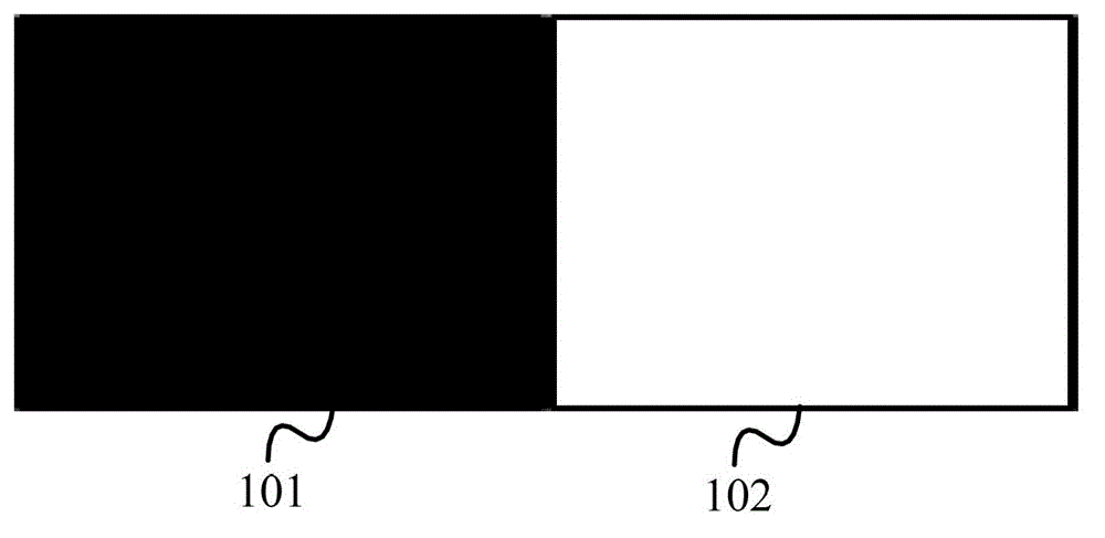
[0002] In traditional display devices, due to the use of uniform backlight, no matter what screen is displayed, the backlight is always bright, such as figure 1 shown, for figure 1 In the display of the image in the traditional display technology, the backlights of the dark area 101 and the bright area 102 are all on, so there is the following problem: for the dark area 101, we do not need or only need a small amount of backlight, and In fact, its backlight intensity is the same as that of the white area 102, which will lead to waste of backlight and light leakage in dark areas
However, this solution can only control the light intensity in a strip or a large area, and cannot control the light intensity in a smaller range
For example, if figure 1 The backlights of the dark area 101 and the bright area 102 are provided by the same light guide strip, but the above-mentioned problems of wasting power consumption and reducing picture quality still cannot be solved.

Method used


Image

  • Backlight local control display device and terminal device
  • Backlight local control display device and terminal device
  • Backlight local control display device and terminal device

Examples


Embodiment Construction

[0029] Hereinafter, preferred embodiments of the present invention will be described in detail with reference to the accompanying drawings. Note that in this specification and the drawings, substantially the same steps and elements are denoted by the same reference numerals, and repeated explanation of these steps and elements will be omitted.

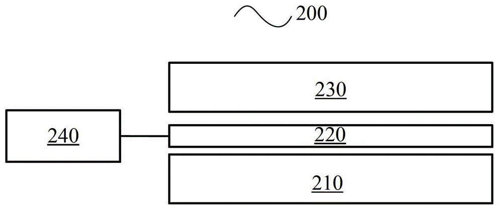
[0030] Below, will refer to figure 2 A display device according to an embodiment of the present invention will be described. figure 2 Shown is a display device 200 for locally controlling backlight according to an embodiment of the present invention, including: a backlight unit 210 , a film 220 with controllable transmittance and reflectance, an optical modulation layer 230 and a control unit 240 .

[0031] Specifically, the backlight unit 210 includes a light guide plate for providing backlight for the display device 200 . For example, the light guide plate may include a plurality of light emitting diodes (LEDs), which may be arra...


PUM


Abstract

The invention provides a display device. The display device is characterized in that the display device comprises a backlight unit which comprises a light guide plate, and is used for providing a backlight for the display device, a transmittance and reflectance controllable film which comprises a number of array units, and is used for carrying out regional control on the backlight, an optical modulation layer which has a number of pixel units, and is used for modulating a light from the transmittance and reflectance controllable film, and a control unit which is connected with a number of array units of the transmittance and reflectance controllable film, and is used for controlling the array units of the transmittance and reflectance controllable film to switch between different states according to a display content. The transmittance and reflectance controllable film is located between the backlight unit and the optical modulation layer. Through the configuration, the display device provided by the invention can dynamically control the backlight to realize backlight regional control, which enhances the dynamic contrast, reduces power consumption and improves the image quality.

Description

technical field [0001] The present invention relates to a display device and terminal equipment for controlling backlight, and more particularly, to a display device and terminal equipment for partially controlling backlight. Background technique [0002] In traditional display devices, due to the use of uniform backlight, no matter what screen is displayed, the backlight is always bright, such as figure 1 shown, for figure 1 In the display of the image in the traditional display technology, the backlights of the dark area 101 and the bright area 102 are all on, so there is the following problem: for the dark area 101, we do not need or only need a small amount of backlight, and In fact, the intensity of the backlight is the same as that of the white area 102, which will result in waste of backlight and light leakage in the dark area. It not only wastes power consumption but also reduces the picture quality; for the bright area, we want it to be brighter, so as to improve ...

Claims


Application Information

Patent Timeline
IPC IPC(8): G09G3/34G02F1/13357
Inventor 张振华尚可
Owner LENOVO (BEIJING) CO LTD
Learn More