
Infinite-rotating automatic clamping mechanism for full-automatic balancing machine
A technology of clamping mechanism and balancing machine, which is applied in the direction of centering/balancing the rotor, etc., can solve the problems of easy failure, high manufacturing cost, complex structure, etc., and achieve the effect of reducing the incidence of failure, simple manufacture and compact structure
- Summary
- Abstract
- Description
- Claims
- Application Information
AI Technical Summary
Problems solved by technology
Method used
Image

Examples
Embodiment Construction
[0024] The present invention will be described in further detail below in conjunction with the accompanying drawings.
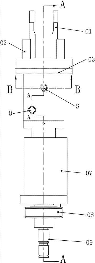
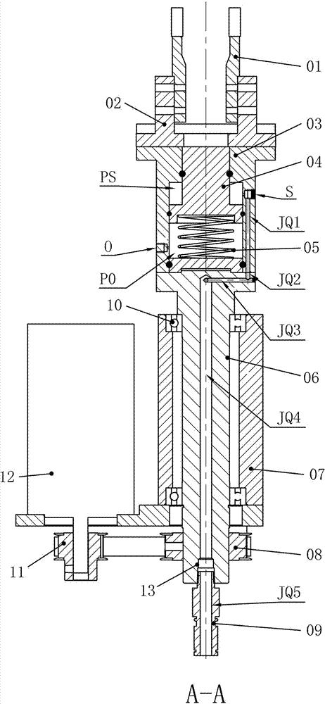
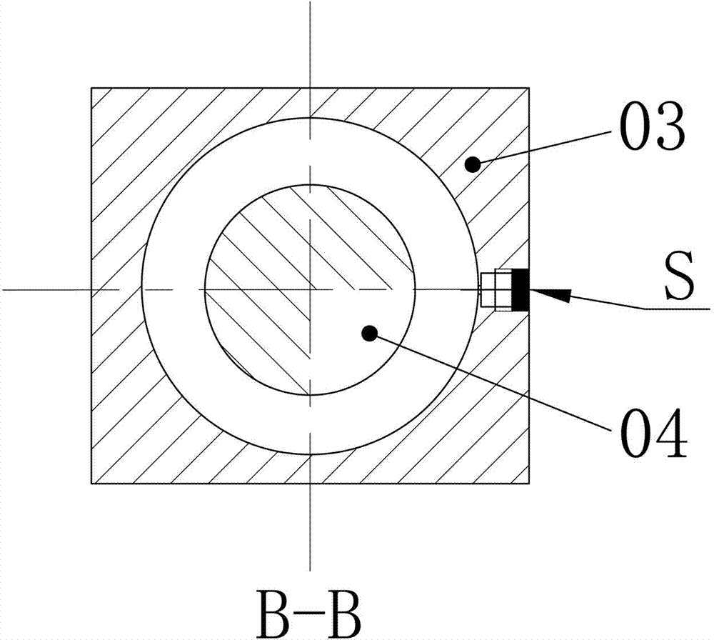
[0025] like figure 1 , 2 , 3, an infinitely rotating automatic clamping mechanism of a fully automatic balancing machine, including air claw 01, finger 02, cylinder 03, connecting rod piston 04, compression spring 05, rotating shaft 06, bearing seat 07, synchronous wheel 08, rotary joint 09 and bearing 10. The air gripper 01 is fixed on the top of the finger 02, the bottom of the finger 02 is sunk in the chute set on the top of the cylinder 03, the finger 02 slides radially in the chute, the cylinder 03 is provided with a cavity, and the bottom of the cylinder 03 passes through The spring base is closed and fixed, a sealing ring is arranged between the spring base and the cylinder body 03 for sealing, and the connecting rod piston 04 is arranged in the cylinder body 03 . The connecting rod piston 04 includes a connecting rod and a piston. The connecting ro...
PUM
 Abstract
Description
Claims
Application Information