Target cell determining method and device

A target cell and cell technology, applied in the field of communication, can solve the problems of increasing handover preparation delay, reducing user experience, call drop, etc., and achieve the effects of reducing handover preparation delay, improving user experience, and improving handover performance

Active Publication Date: 2014-07-23
DATANG MOBILE COMM EQUIP CO LTD
View PDF4 Cites 20 Cited by
  • Summary
  • Abstract
  • Description
  • Claims
  • Application Information

AI Technical Summary

Problems solved by technology

[0017] Embodiments of the present invention provide a method and device for determining a target cell, which are used to solve the process of determining the target cell for the UE to be

Method used


Image

  • Target cell determining method and device
  • Target cell determining method and device
  • Target cell determining method and device

Examples


Embodiment 1

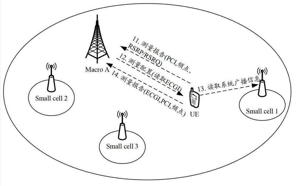
[0093] Embodiment 1. Assuming that 5 small cells are deployed within the coverage of macro cell A (macro cell A), namely small cell1~small cell5, see for network topology Figure 5 As shown, small cell 1 and small cell 3 have the same operating frequency and PCI, and the PCIs of other small cells are different. In this embodiment, each base station adopts Method 1 to obtain the first location information of each cell controlled by itself, and the second location information is the longitude and latitude information of the location of the UE; for the process of determining the target cell by the macro base station provided in this embodiment, see Image 6 As shown, including the following steps:

[0094] Step 61: The macro base station A obtains the first location information of each cell controlled by itself, and the small base station obtains the first location information of each cell controlled by itself;

[0095] Specifically, the operator configures the first location informati...

Embodiment 2

[0112] Example 2. Still using Figure 5 The network topology shown is an example. This embodiment is similar to Embodiment 1, but the difference is: In this embodiment, macro base station A adopts method 1 to obtain the first location information of each cell controlled by itself, and is similar to that of macro base station A. Adjacent small base stations adopt mode 2 to obtain the first location information of each cell controlled by themselves;

[0113] Specifically, when the operator deploys the macro base station A (that is, the base station where the macro cell A is located), the first location information of the macro cell A is configured; each small base station obtains the information of the small cell controlled by itself through its own positioning device. The first location information.

Embodiment 3

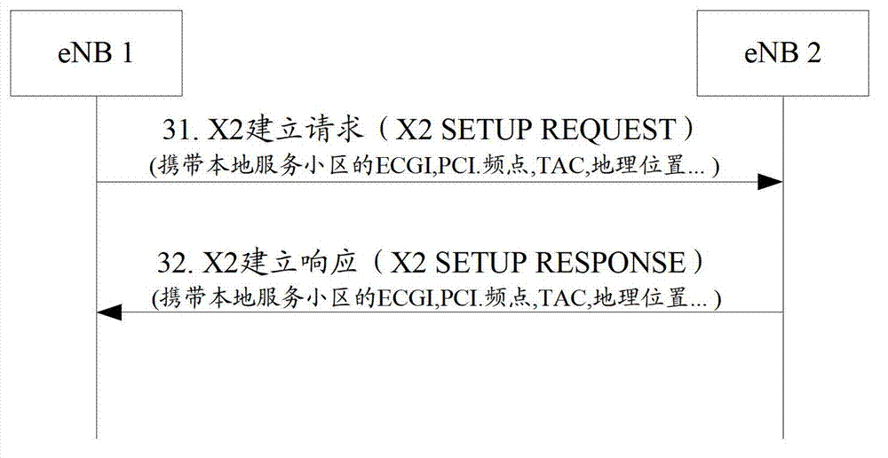
[0114] Example 3. Still using Figure 5 The network topology shown is an example. In this embodiment, the small eNB1 has established an interface connection with the macro base station A (such as the X2 interface), and then the small cell1 serving cell of the small eNB1 changes its configuration information (such as PCI and changes The latter PCI is exactly the same as the PCI of small cell3); for the process of determining the target cell by the macro base station in this embodiment, see Figure 7 As shown, including the following steps:

[0115] Step 71: The small eNB1 sends an interface signaling message to the macro base station A, and the interface signaling message carries the updated configuration information of the small cell1;

[0116] Wherein, the configuration information includes configuration parameters (the configuration parameters include operating frequency and PCI, ECGI, TAC, etc.) and first location information;

[0117] Step 72: After receiving the interface signal...


PUM


Abstract

The embodiment of the invention discloses a target cell determining method and device. The problems of long switching preparation delay and easy dropping in the prior art are solved. The method provided by the embodiment of the invention comprises the steps that after a service base station receives a measurement report sent by UE served by the service base station, the service base station searches adjacent cells matching the work frequency point and PCI of a target cell of a UE report in the measurement report from the adjacent cell relationship table, and takes the found adjacent cells as intermediate cells; and if at least two intermediate cells are found, according to first position information corresponding to each intermediate cell locally saved and second position information in the measurement report, the target cell of the UE report is determined from at least two intermediate cells. According to the embodiment of the invention, the UE simply needs to report the measurement report, and the target cell can be accurately determined; the switching preparation delay is reduced; and the probability of dropping caused by too long delay is reduced.

Description

Technical field [0001] The present invention relates to the field of communication technology, and in particular to a method and equipment for determining a target cell. Background technique [0002] In the heterogeneous hierarchical deployment network of the Long Term Evolution (LTE) system, the macro cell layer and the small cell layer may overlap, that is, within the coverage of the macro cell , May deploy small cells at the same time. The so-called small cell refers to a cell provided by a low-power base station with a lower transmit power than an ordinary macro base station. For example, pico cells, femto cells, etc. are all typical small cells. [0003] The physical layer of the LTE system defines a total of 504 Physical Cell Identifiers (PCI). In order to avoid inter-cell interference and enable the base station (eNB) to correctly identify each neighboring cell, the PCI configuration needs to meet the following two requirements: [0004] One is collision-free, that is, any t...

Claims


Application Information

Patent Timeline
IPC IPC(8): H04W36/08H04W24/08
Inventor 王彦张大钧
Owner DATANG MOBILE COMM EQUIP CO LTD
Why Eureka
Try Eureka