Gas cylinder, in particular high-pressure gas cylinder

A high-pressure cylinder and cylinder technology, applied in fluid pressure actuating devices, engine seals, springs, etc., can solve problems such as difficulty in air pressure sealing, and achieve the effect of preventing gas loss

Active Publication Date: 2014-07-23
HYDAC TECH GMBH
View PDF5 Cites 8 Cited by
  • Summary
  • Abstract
  • Description
  • Claims
  • Application Information

AI Technical Summary

Problems solved by technology

[0003] In the presence of high pressures in the pressure chamber during operation, the sealing of the gas pressure against the ambient air is very difficult even when relatively large molecular working gases such as N2 are involved

Method used


Image

  • Gas cylinder, in particular high-pressure gas cylinder
  • Gas cylinder, in particular high-pressure gas cylinder
  • Gas cylinder, in particular high-pressure gas cylinder

Examples


Embodiment Construction

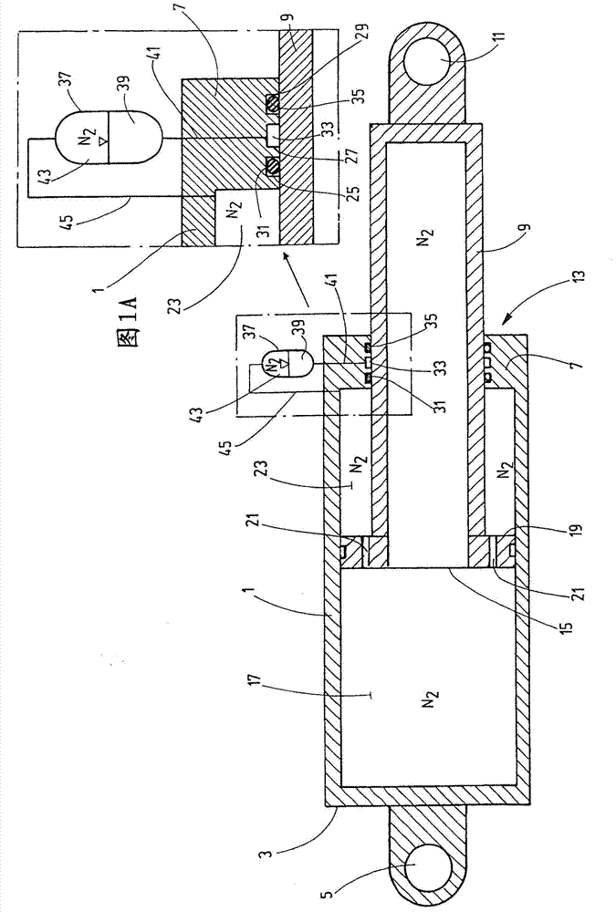
[0034] exist figure 1 The exemplary embodiment shown in has a cylinder liner 1 with a bearing bore 5 at its closed end 3 . At the opposite end, the cylinder liner 1 has a cylinder end cover part 7 which forms a sealed guide passage for a piston rod 9 on whose outer end a bearing is provided Hole 11. The sealing of the piston rod 9 relative to the end cap part 7 takes place by means of a sealing device 13 . The piston rod 9 has the shape of a cylindrical hollow body, thus forming a tube which is open at its inner end 15 towards the pressure chamber 17 of the cylinder liner 1 . The pressure chamber 17 is filled (via a filling connection not shown) with a working gas at high pressure, for example N2. On the open end 15 of the piston rod 9 there is a piston-shaped guide element 19 which is guided on the inner wall of the cylinder liner 1 during the movement of the piston rod 9 . Channels 21 are provided in the guide part 19 , each channel communicating the pressure chamber 17 ...


PUM


Abstract

The invention relates to a gas cylinder, in particular a high-pressure gas cylinder, the cylinder tube (1) of which has a piston rod (9) that is passed through a sealing arrangement (13) by which the gas pressure prevailing in the pressure chamber (23) of the cylinder tube (1) is sealed off against the ambient pressure. The invention is characterized in that the sealing arrangement (13) has a compressed oil chamber (33) between at least one sealing element (31) adjacent to the pressure chamber (23) and at least one more sealing element further away from the pressure chamber (23), into which oil chamber oil can be pressed in by means of a supply device (51) at a pressure that is equal to or higher than the respective gas pressure prevailing in the pressure chamber (23) of the cylinder tube (1).

Description

technical field [0001] The invention relates to a cylinder, in particular a high-pressure cylinder, the cylinder liner of which has a piston rod which is guided through a sealing device which separates the air pressure present in the pressure chamber of the cylinder liner from the Ambient pressure tight. Background technique [0002] Such a cylinder as a plunger cylinder can be used particularly advantageously as an energy storage cylinder in a device for energy recovery. In such an application, as is shown for example in document DE 10 2008 034 582 A1, the piston rod of the cylinder is connected to the movable element of the associated working device. The movable element may for example be a boom of an excavator or a machine for material transfer or similar operations. When the movable element is lowered, the potential energy of the movable element and of the load connected thereto is stored by means of the cylinder, in order to at least partially compensate for the corre...

Claims


Application Information

Patent Timeline
Patent Type & Authority Applications(China)
IPC IPC(8): F15B15/14F16J15/40F16J15/56F16F9/36
CPCF15B15/1461F16F9/0209F16F9/0236F16F9/3278F16F9/362F16F9/365F15B1/24F16J15/40F16J15/46
Inventor F·鲍尔D·费尔德
Owner HYDAC TECH GMBH
Why Eureka
Try Eureka