Power conversion device

A technology of power conversion devices and inverters, which is applied to output power conversion devices, electrical components, and conversion of AC power input to DC power output, etc., which can solve problems such as difficulty in securing the installation site and rising cost of test equipment

Active Publication Date: 2014-07-23
TOSHIBA MITSUBISHI-ELECTRIC IND SYST CORP
View PDF10 Cites 1 Cited by
  • Summary
  • Abstract
  • Description
  • Claims
  • Application Information

AI Technical Summary

Problems solved by technology

At this time, when there are AC motors with different voltage levels, it is necessary to prepare a power conversion device for each volt

Method used


Image

  • Power conversion device
  • Power conversion device
  • Power conversion device

Examples


Embodiment 1

[0024] Below, refer to Figure 1 to Figure 3 , the power conversion device according to Embodiment 1 of the present invention will be described.

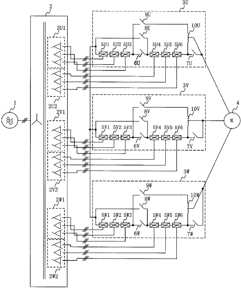
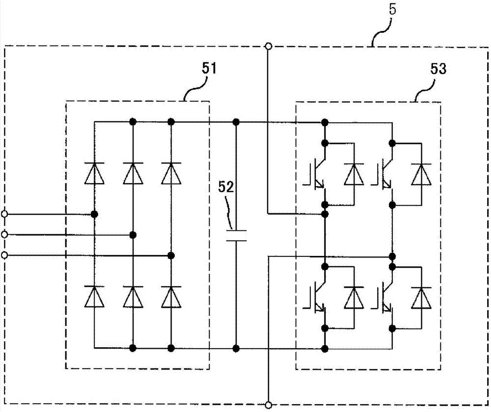
[0025] figure 1 It is a circuit configuration diagram of the power conversion device according to Embodiment 1 of the present invention. A high-voltage three-phase AC voltage is supplied from the AC power source 1 to the input transformer 2 . The input transformer 2 has secondary winding groups 2U1, 2U2, 2V1, 2V2, 2W1, and 2W2 each having a plurality of insulated secondary windings, and supplies AC power from the secondary winding groups 2U1, 2U2 to the U-phase power converter 3U. Primary winding groups 2V1 and 2V2 supply AC power to V-phase power converter 3V, and secondary winding groups 2W1 and 2W2 supply AC power to W-phase power converter 3W. The U-phase power converter 3U, the V-phase power converter 3V, and the W-phase power converter 3W respectively output single-phase AC voltages with a phase difference of 120° from each...

Embodiment 2

[0034] Figure 5 It is a circuit configuration diagram of a power conversion device according to Embodiment 2 of the present invention. For each part of this embodiment 2, will be with figure 1 The same parts of the power conversion device according to Embodiment 1 of the present invention are denoted by the same symbols, and description thereof will be omitted. The difference between Embodiment 2 and Embodiment 1 is that the number of secondary windings belonging to each secondary winding group of the input transformer 2A is changed from 3 to 2, and the unit inverters of each phase are accordingly The number of units has been changed from 6 to 4.

[0035] The operations of the second embodiment are all the same as those of the first embodiment. In Example 1, the phase voltage obtained by adding six unit inverters 6 is output in the series connection mode, and the output voltage becomes half of the output voltage in the parallel connection mode, but in this Example 2, the ser...

Embodiment 3

[0038] Figure 6 It is a circuit configuration diagram of main parts of a power conversion device according to Embodiment 3 of the present invention. The main part described here is the U-phase power conversion unit, and illustration of other parts is omitted. For each part of this embodiment 3, with figure 1 In the U-phase power conversion unit of the power conversion device according to Embodiment 1 of the present invention, the same parts are denoted by the same symbols, and description thereof will be omitted. The difference between the present embodiment 3 and the embodiment 1 is that the unit inverters 5U7, 5U8 and 5U9 are added to the U-phase power converter part 3UB, and the structure of the unit inverters is changed from 6 units to 9 units; Add switches 11U, 12U, and 13U so that three sets of unit inverters can be connected in parallel; and accordingly, the balance reactor 10U is changed to three balance reactors 10UA, 10UB, and 10UC.

[0039] In Example 3, for the...


PUM


Abstract

Provided is a power conversion device whereby different voltage classes can be outputted by a single power conversion device without reducing the rated capacity. The present invention is configured from: an input transformer (2) having 3 K (where K is an integer of 2 or greater) secondary coils, an alternating-current power source (1) being connected to a primary coil; and three power conversion units (3) connected one-each to the secondary coils and configured so as to each output three-phase phase voltage using K unit inverters (5) for outputting single-phase alternating-current voltage at a desired frequency. The power conversion units (3) are configured so as to be switched between a series-connection mode for connecting the outputs of the K unit inverters (2) in series, and a parallel-connection mode for dividing the K unit inverters into a plurality of groups, connecting the outputs of the unit inverters within each group in series, and connecting the outputs of the plurality of inverter groups in parallel.

Description

[0001] References to related applications [0002] This application is based on and claims the benefit of priority from Japanese Patent Application No. 2011-253581 with a filing date of November 21, 2011, the entire contents of which are incorporated herein by reference. technical field [0003] The present invention relates to a power conversion device capable of changing the rated output voltage. Background technique [0004] Conventionally, as one of the power conversion devices that output multi-phase alternating current, it is known that the output side of the single-phase inverter Each phase is connected in series to realize a multiplexed power conversion device. [0005] It has been proposed as a power conversion device used in various test power supplies and other general industries, etc., by connecting the output side of the single-phase inverter in series to form each phase and realizing multiple devices that can operate stably scheme (for example, refer to Paten...

Claims


Application Information

Patent Timeline
IPC IPC(8): H02M7/48H02M7/493
CPCH02M7/493H02M7/49H02M7/5395
Inventor 出利叶大辅下浦拓二黑岩昭彦
Owner TOSHIBA MITSUBISHI-ELECTRIC IND SYST CORP
Why Eureka
Try Eureka