Injector clamping device

The technology of a clamping device and a syringe, which is applied in the field of medical devices, can solve the problems of complex structure, high cost, inconvenient use, etc., and achieve the effects of simple structure, low cost and reduced space occupation.

Active Publication Date: 2014-07-30
SINO MEDICAL DEVICE TECH
View PDF4 Cites 5 Cited by
  • Summary
  • Abstract
  • Description
  • Claims
  • Application Information

AI Technical Summary

Problems solved by technology

[0006] However, the above-mentioned first and second types of claws need to be lifted and placed in the claws on the slider when the slider moves close to the syringe push handle during use, which is inconvenient to use; the third type of claw is made of The realization of gear drive requires a certain space on the slider to install the gear, the structure is complex and the cost is high

Method used


Image

  • Injector clamping device
  • Injector clamping device
  • Injector clamping device

Examples


Embodiment Construction

[0034] In order to have a clearer understanding of the technical features, purposes and effects of the present invention, the specific implementation manners of the present invention will now be described in detail with reference to the accompanying drawings.

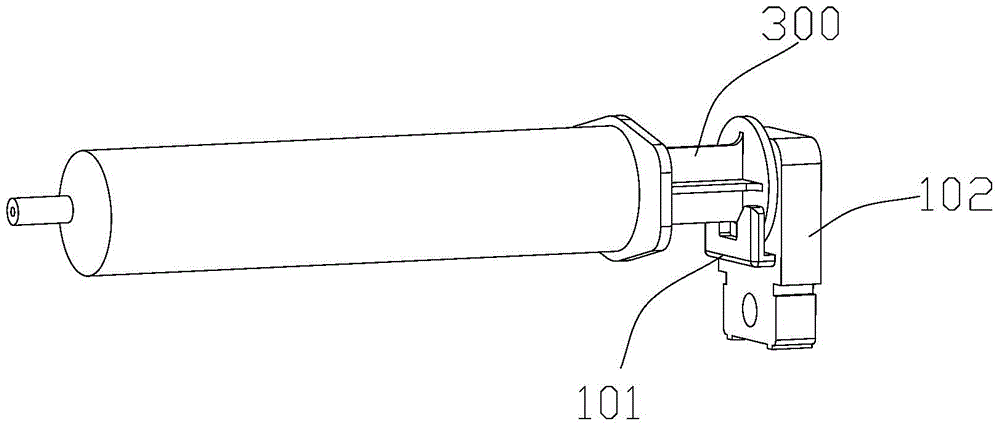
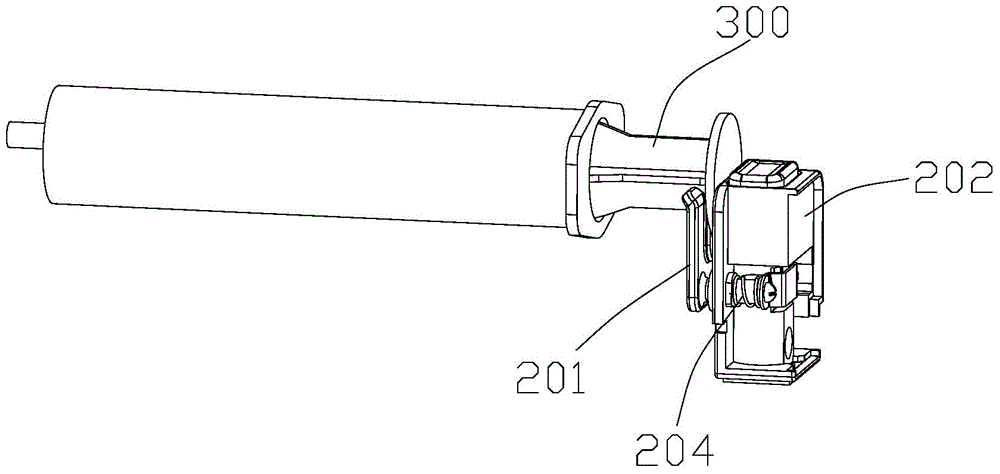
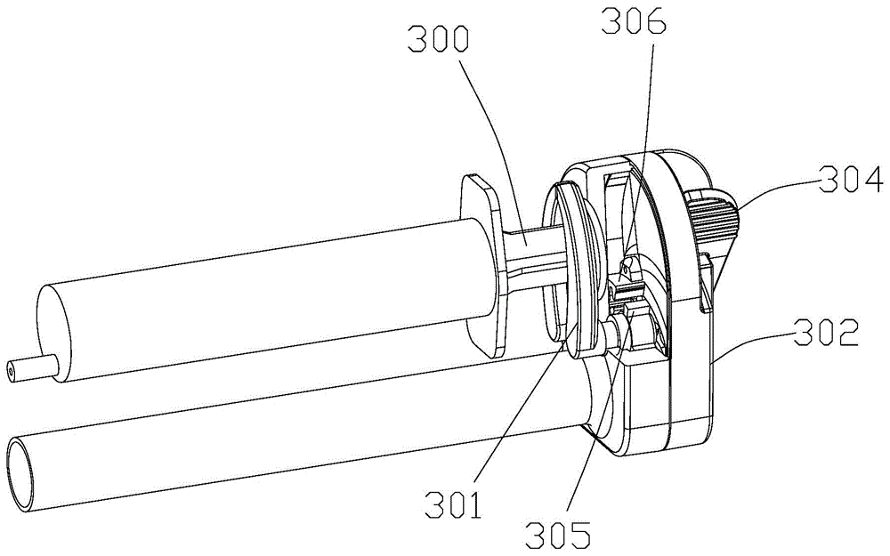
[0035] Such as Figure 4-8 As shown, the syringe clamping device according to an embodiment of the present invention is used to clamp the syringe 100 on the syringe pump for injection operation. The syringe clamping device may include a slider mechanism, an engaging mechanism 20 and a clamping mechanism 30; the slider mechanism can slide through the screw rod 200 of the syringe pump, and can move correspondingly according to the position of the push handle 110 of the syringe 100; the engaging mechanism 20 can The movement is set in the slider mechanism, which can be detachably engaged with the screw rod 200 by moving, so that the slider mechanism can be positioned on the screw rod 200; the clamping mechanism 30 is rotat...


PUM


Abstract

The invention relates to an injector clamping device, which comprises a sliding block mechanism, a meshing mechanism and a clamping mechanism, wherein the sliding block mechanism is arranged on an injection pump screw in a sliding penetration way; the meshing mechanism is separably meshed with the screw in a movement way; the clamping mechanism rotates to clamp or loosen an injector under the driving of movement of the meshing mechanism; the sliding block mechanism comprises a hollow sliding block main body with a through hole allowing the screw to penetrate; the meshing mechanism is arranged in the sliding block main body in a way of moving backwards and forwards in directions close to and away from the through hole; the clamping mechanism is inserted into the sliding block main body in a rotating way, and is clamped with the meshing mechanism. The injector clamping device is simple in structure, low in cost, convenient to use and suitable for the clamping of injectors in various specifications on an injection pump.

Description

technical field [0001] The invention relates to the field of medical instruments, in particular to a syringe clamping device. Background technique [0002] In the existing syringe pump, the clamping of the syringe on it is usually realized by claws, and there are several ways as follows: [0003] 1. Fixed claw: such as figure 1 As shown, the claw 101 is fixedly arranged on a slider 102, and the push handle 300 of the syringe is clamped in the gap between the claw 101 and the slider 102, and the push handle 300 of the syringe is pushed back and forth by the slider 102; It is difficult for this kind of fixed claw to clamp the push handle 300 tightly, and there is a gap between the push handle 300 and the claw 101 . [0004] 2. Telescopic jaws: such as figure 2 As shown, the claw 201 is installed on the slider 202 through the spring 204, and the stretching force of the spring 203 drives the claw 201 to sandwich the push handle 300 of the syringe; [0005] 3. Rotary claw: s...

Claims


Application Information

Patent Timeline
Patent Type & Authority Applications(China)
IPC IPC(8): A61M5/31
Inventor 吴海明张宏赖刚汪栋辉王争孙继蕃梁祥锦周杰周贤林张昭
Owner SINO MEDICAL DEVICE TECH
Why Eureka
Try Eureka