De-foaming and recycling system and process

A recirculation and defoaming technology, applied in filtration loop, foam dispersion/prevention, filtration separation, etc., can solve the problems of product quality impact, long defoaming time, and insignificant effect.

Active Publication Date: 2014-07-30
TDK DALIAN
View PDF4 Cites 12 Cited by
  • Summary
  • Abstract
  • Description
  • Claims
  • Application Information

AI Technical Summary

Problems solved by technology

It takes a long time to stand for defoaming, but the cost is low, and the effect is not obvious for liquid materials with high viscosity
High temperature degassing will accelerate the bubble escape rate, but the degassing time is long, and the high temperature will easily affect the physical and chemical properties of the liquid material
Although ultrasonic vibration degassing has a fa...

Method used


Image

  • De-foaming and recycling system and process
  • De-foaming and recycling system and process

Examples


Embodiment 1

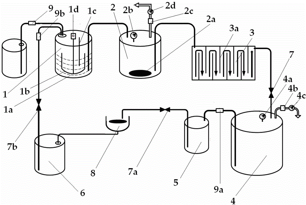
[0022]The new liquid material enters the stirring tank under the action of the vacuum pump and the suction pipe for uniform speed and constant temperature stirring. The stirred liquid material is sent into the first vacuum defoaming tank through the metal pipeline under the action of vacuum suction. The first degassing treatment is carried out, and the liquid material after the first degassing is sent to the second waterfall degassing tank through the metal pipeline under the action of vacuum suction for the second degassing treatment, and the liquid material after the second degassing is vacuum After being filtered by the first filter under the action of suction, it is sent to the third vacuum degassing tank for three times of degassing treatment, and the liquid material after three times of degassing enters the storage tank under the action of vacuum suction, and then filtered through the second filter After the disc spin coating operation, the remaining liquid material flows...

Embodiment 2

[0024] The degassing and recycling process of embodiment 2 is the same as that of embodiment 1, and the process parameter conditions of the agitated tank are: the temperature in the tank is 40° C., and the rotational speed of the agitator is 30 rpm; the process parameter conditions of the first vacuum degassing tank are: ultrasonic vibration frequency It is 60Hz, the vacuum degree is -90Kp, and the degassing time is 90 minutes; the process parameter condition of the second waterfall type degassing tank is: the degassing time is 70 minutes; the process parameter condition of the third vacuum degassing tank is: the vacuum degree is - 90Kp. The liquid material is degassed under the conditions of the above process parameters, the air bubble rate is 0.1% per thousand discs after spin coating, and the diameter of the bubbles on the disc surface is less than 40 μm.

Embodiment 3

[0026] The degassing and recycling process of embodiment 3 is the same as that of embodiment 1. The process parameter conditions of the agitated tank are: the temperature in the tank is 44° C., and the rotational speed of the agitator is 40 rpm; the process parameter conditions of the first vacuum degassing tank are: ultrasonic vibration frequency It is 70Hz, the vacuum degree is -100Kp, and the degassing time is 70 minutes; the process parameter condition of the second waterfall type degassing tank is: the degassing time is 90 minutes; the process parameter condition of the third vacuum degassing tank is: the vacuum degree is - 100Kp. The liquid material is degassed under the conditions of the above process parameters, the air bubble rate is 0.1% per thousand discs after spin coating, and the diameter of the bubbles on the disc surface is less than 40 μm.


PUM


Abstract

The invention belongs to the technical field of charge-discharge control devices and methods for de-foaming mechanisms, and discloses a de-foaming and recycling system and process. A new liquid material enters a stirring tank under the action of a vacuum pump and a suction pipe and is stirred at constant speed and constant temperature; the stirred liquid material is fed into a first vacuum de-foaming tank through a metal pipeline under the action of vacuum suction force and is de-foamed primarily; the liquid material which is de-foamed primarily is fed into a second cascade type de-foaming tank through a metal pipeline under the action of the vacuum suction force and is de-foamed secondarily; the liquid material which is de-foamed secondarily is fed into a third vacuum de-foaming tank through a metal pipeline under the action of the vacuum suction force and is de-foamed for the third time; the liquid material which is de-foamed for the third time; enters a storage tank under the action of the vacuum suction force and is directly subjected to optical disk spin-coating operation; after the optical disk spin-coating operation is performed, the remaining liquid material flows into a recycling tank, flows into the stirring tank under the action of the vacuum suction force, and is mixed with a new liquid material for continuous use so as to be recycled. The system and the process are low in cost, easy to operate and high in de-foaming efficiency, and cannot affect the physical and chemical performances of the de-foamed liquid material; the liquid material can be continuously fed, de-foamed, used and recycled.

Description

technical field [0001] The invention relates to a defoaming and recycling system and its process, and belongs to the technical field of a defoaming mechanism feeding and discharging control device and method. Background technique [0002] In the spin coating process of the optical disc protective layer, if the spin coating liquid contains a bubble, the bubble will stay on the surface of the optical disc. When the laser reader focuses the beam to read data, the existence of air bubbles will cause the laser to fail to focus, resulting in data reading failure. Therefore, in the spin-coating preparation of the optical disc protective layer, no air bubbles are allowed in the protective layer, that is, no air bubbles are required in the spin-coating liquid. At present, the defoaming process mainly includes centrifugal defoaming, static defoaming, high temperature defoaming, ultrasonic vibration defoaming, vacuum defoaming, chemical defoaming, etc. The centrifugal defoaming time ...

Claims


Application Information

Patent Timeline
IPC IPC(8): B01D19/02B01D36/00
Inventor 徐晓东曲文超郭丽娟
Owner TDK DALIAN
Why Eureka
Try Eureka