Centrifugal vacuum defoaming equipment for online continuous treatment

A vacuum defoaming and centrifugal technology, which is applied in the direction of liquid degassing, separation method, foam dispersion/prevention, etc., can solve the problems of incomplete slurry treatment, large slurry bubble content, difficult maintenance and repair, etc., and achieve the design High efficiency, reasonable mechanism of action, and easy processing

Inactive Publication Date: 2021-12-07
LIUZHOU HUT CHEM MACHINERY
View PDF5 Cites 0 Cited by
  • Summary
  • Abstract
  • Description
  • Claims
  • Application Information

AI Technical Summary

Problems solved by technology

This technical solution has the following deficiencies: 1. The slurry flows back and forth from the bottom to the top, and is discharged from the upper part, and the slurry air bubble content after discharge is relatively large; 2. The slurry directly passes through the centrifugal chamber quickly, resulting in The slurry treatment is not thorough, and the slurry direction from bottom to top will leave slurry residue at the bottom of the pan; 3. The structure is more complicated, the cost is high, and the maintenance and repair are relatively difficult

Method used


Image

  • Centrifugal vacuum defoaming equipment for online continuous treatment
  • Centrifugal vacuum defoaming equipment for online continuous treatment
  • Centrifugal vacuum defoaming equipment for online continuous treatment

Examples


Embodiment

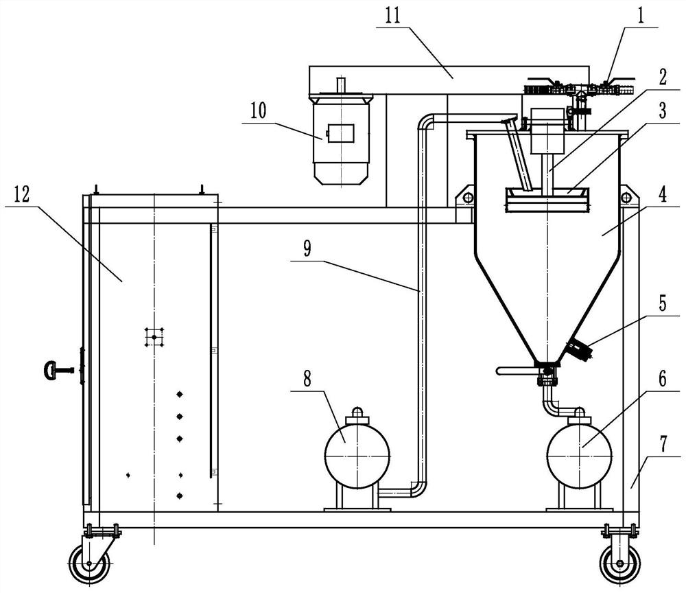
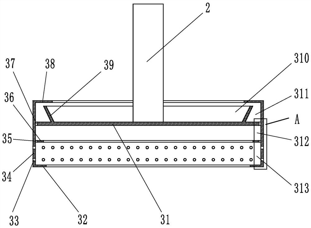
[0027] Embodiment: a kind of centrifugal vacuum degassing equipment of online continuous processing, such as Figure 1-Figure 3 Shown, comprise frame 7, feed pump 8, discharge pump 6, defoaming disc 3, rotating shaft 2, power unit 10 and the tank body 4 that is installed on the frame, transmission system 11, described feed pump 8 The defoaming disc 3 is communicated with the defoaming disc 3 through the feeding pipeline 9, the defoaming disc 3 is connected with the rotating shaft 2, and the rotating shaft is connected with the power device through the transmission system, and the tank body 4 is a closed container, and a vacuum port 1 is arranged on it , by vacuuming the inside of the tank to be in a negative pressure or vacuum state, to achieve the purpose of vacuum defoaming. There is a discharge port at the lower end of the tank body, and the discharge port communicates with the discharge pump 6 . The bottom of the tank body is provided with a liquid level gauge 5, and insp...


PUM


Abstract

The invention relates to centrifugal vacuum defoaming equipment for on-line continuous treatment. The equipment comprises a rack, a feeding pump, a discharging pump, a defoaming disc, a rotating shaft, a power device, a tank body and a transmission system, wherein the tank body and the transmission system are installed on the rack, the feeding pump communicates with the defoaming disc through a feeding pipeline, the defoaming disc is connected with the rotating shaft, the rotating shaft is connected with the power device through the transmission system, the discharging pump communicates with the discharge hole of the tank body, the defoaming disc comprises a surrounding plate, and an annular upper baffle plate, a circular web plate, an annular pressure baffle plate and an annular lower baffle plate which are sequentially connected with the surrounding plate from top to bottom, a crushing baffle ring is arranged on the circular web plate, a crushing membranization cavity, a centrifugal separation cavity, a membranization cavity and a material throwing cavity are formed in the defoaming disc, and a plurality of material throwing holes are formed in the surrounding plate of the material throwing cavity. The defoaming disc used in the equipment is simple in structure and good in defoaming effect, can realize rapid and efficient defoaming of slurry, greatly improves defoaming efficiency, and improves the defoaming consistency of slurry of different batches.

Description

technical field [0001] The invention relates to a degassing device, in particular to a centrifugal vacuum degassing device for online continuous processing of slurry. Background technique [0002] The key part of the defoaming equipment is the defoaming tray. The structure of the defoaming tray commonly used in the factory is as follows: Figure 4 shown. The existing slurry defoaming technology is mainly to cut the slurry by using the small holes on the defoaming plate in a vacuum state, and use the hydraulic impact and the baffle to break and separate the air bubbles in the slurry. The slurry is re-filmed to degas the air bubbles. The main disadvantage of the prior art is that the efficiency is low, and the stability of the defoaming effect of different batches of slurry is insufficient. [0003] Chinese patent application 202110066319.4 discloses a continuous defoaming reciprocating gravity distribution discharge tray, including a tray body, a partition cover and a parti...

Claims


Application Information

Patent Timeline
IPC IPC(8): B01D19/02
CPCB01D19/02B01D19/0057B01D19/0042
Inventor 李行可
Owner LIUZHOU HUT CHEM MACHINERY
Why Eureka
Try Eureka