Power equipment base fastening device and fixing method

A technology for power equipment and fastening devices, applied in infrastructure engineering, construction, etc., can solve problems such as installation difficulties, loose fasteners, and the existence of dangerous factors, and achieve the effect of convenient construction and convenient installation.

Inactive Publication Date: 2014-07-30
赵东京 +1
View PDF9 Cites 4 Cited by
  • Summary
  • Abstract
  • Description
  • Claims
  • Application Information

AI Technical Summary

Problems solved by technology

Moreover, after the equipment is put into use, the vibration will cause the loosening of the fasteners, which need to be tightened regularly, which not only has risk factors, but also requires regular maintenance.
[0003] The traditional construction technology still uses anchor bolts for direct fixing. The fixing method of this structure is relatively firm, but there is a problem that it is difficult to adjust the position, because the anchor bolts are formed during the pouring of the concrete foundation, or It is carried out with expansion bolts, and the adjustability is very poor, which makes installation difficult
[0004] There is also a casing-type anchor plate structure, and the fastening device of this structure has the problem of difficulty in installation

Method used


Image

  • Power equipment base fastening device and fixing method
  • Power equipment base fastening device and fixing method
  • Power equipment base fastening device and fixing method

Examples


Embodiment Construction

[0036] Such as Figure 1 to Figure 8 as shown,

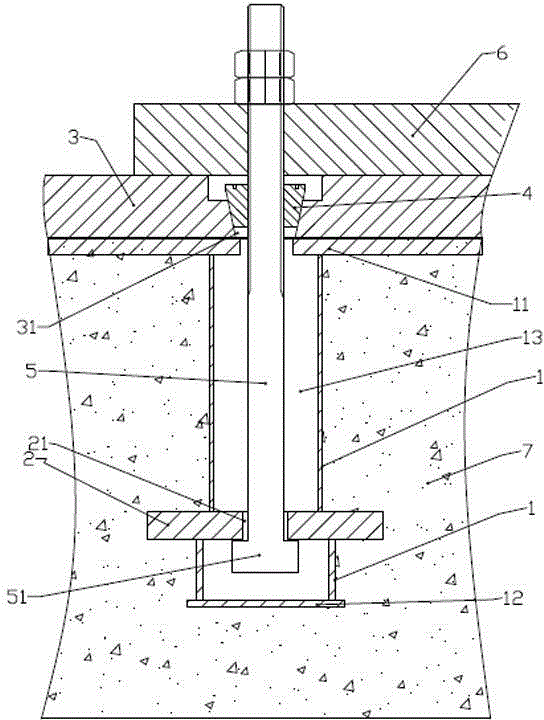
[0037] A power equipment base fastening device includes the following parts.

[0038] -Concrete foundation 7 by pouring and solidification molding, this is foundation work.

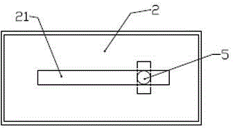
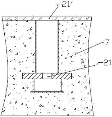
[0039] Make a cuboid box body 1, which is formed by welding thick steel plates. The top plate 11 and the bottom plate 12 are extended to both sides. The extension design has two purposes, one is to increase the bonding force with the concrete foundation, and the other is to provide the following The welding between the steel backing plates provides convenience. The middle and lower part of the box cavity 13 is provided with a horizontal anchor plate 2, and the anchor plate 2 is welded into one body with the box body and the two sides of the anchor plate extend to the concrete foundation outside the box body. Open a long hole 21 on the top, as figure 2 As shown; the anchor plate 2 is the main part bearing the tension of the bolt, and it adopts a thicker...


PUM


Abstract

The invention relates to a power equipment base fastening device, mainly aiming at solving the problems of low installation accuracy and inconvenience in maintenance. A box body part in the device is cast and fixed in a concrete foundation, and elongated holes are respectively formed in an anchor plate and a top plate of the box body; a steel cushion plate and an elongated T-shaped bolt are placed and fixedly welded on the upper side of the box body, the T-shaped bolt head of the T-shaped bolt is clamped in the elongated hole in the anchor plate, and the upper section of the T-shaped bolt is spirally fastened and connected with a conical nut in the steel cushion plate; a power equipment base is placed on the upper side of the steel cushion plate and is fastened and connected with the T-shaped bolt through a nut. The invention additionally discloses a power equipment fixing method. Firstly, since the device has a self-locking function, the problem that power equipment gets loose due to the vibration of the power equipment is solved; secondly, the adjustment during installation can be realized.

Description

technical field [0001] The invention relates to the technical field of power equipment installation bases, in particular to a power equipment base fastening device and a fixing method. Background technique [0002] In the power equipment installation project, the dynamic load of the power equipment and the vibration factor of the power equipment should be considered. Moreover, after the equipment is put into use, the vibration will cause the loosening of the fasteners, which need to be tightened regularly, which not only has risk factors, but also requires regular maintenance. [0003] The traditional construction technology still uses anchor bolts for direct fixing. The fixing method of this structure is relatively firm, but there is a problem that it is difficult to adjust the position, because the anchor bolts are formed during the pouring of the concrete foundation, or It is carried out with expansion bolts, and the adjustability is very poor, which makes installation d...

Claims


Application Information

Patent Timeline
Patent Type & Authority Applications(China)
IPC IPC(8): E02D27/44
Inventor 赵东京肖琳琳
Owner 赵东京
Why Eureka
Try Eureka