Thermal energy rotor power equipment and work-acting method thereof
What is AI technical title?
AI technical title is built by PatSnap AI team. It summarizes the technical point description of the patent document.
A technology of power equipment and rotors, applied in the field of thermal power equipment, can solve the problems of internal combustion star engine with complex structure, high manufacturing cost, and high cost, and achieve the effects of light weight, high operating speed, and small vibration
Active Publication Date: 2015-11-18
郭远军
View PDF7 Cites 0 Cited by
Summary
Abstract
Description
Claims
Application Information
AI Technical Summary
This helps you quickly interpret patents by identifying the three key elements:
Problems solved by technology
Method used
Benefits of technology
Problems solved by technology
[0017] The invention overcomes the problems of high cost of the expansion chamber, compression chamber, heater, cooling chamber, regenerator, etc. in the external combustion engine, and the heat loss is 2-3 times that of the internal combustion engine; it overcomes the need for expansion in the organic Rankine cycle system Engine or steam turbine, the technical problem of high manufacturing cost; overcome the problem of complex structure and high manufacturing cost of internal combustion radial engine
Method used
Image
Click on the blue label to locate the original text in one second.
Reading with bidirectional positioning of images and text.
Examples
Embodiment 1
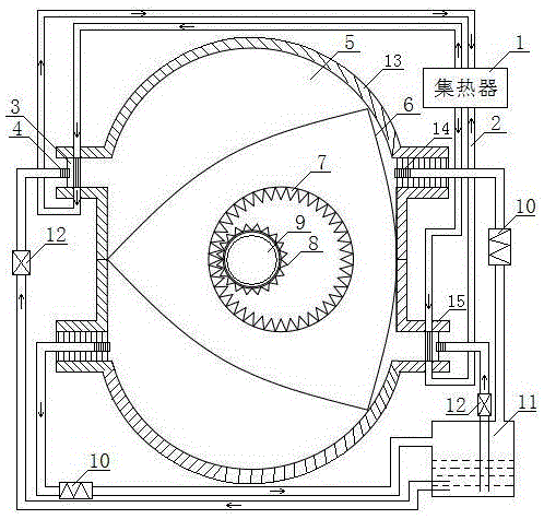
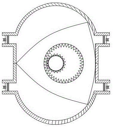
[0031] A thermal energy rotor power equipment, including a heat collector 1, an insulation pipe 2, a gasification reactor 3, an atomizer 4, a cylinder 5, a triangular rotor 6, an inner ring gear 7, a gear 8, an output shaft 9, and a cooler 10 , liquid storage tank 11, pressure valve 12, insulation layer 13, automatic exhaust valve 14 and casing 15; Triangular rotor 6 is arranged in casing 15, and the center of triangular rotor 6 is provided with ring gear 7, and ring gear 7 Matching gear 8, gear 8 is fixed on the output shaft 9, triangular rotor 6 divides the cylinder 5 into three uniform independent spaces, the ratio of the number of teeth of the inner ring gear 7 to the gear 8 is 3:2, and the two sides of the cylinder 5 are respectively equipped with Gasification reactor 3 and automatic exhaust valve 14; heat collector 1 is connected to gasification reactor 3 through insulation pipe 2, and atomizer 4 is provided at the inlet end of gasification reactor 3, and atomizer 4 is co...
Embodiment 2
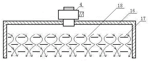
[0033] As in the star-shaped thermal power equipment in Example 1, the gasification reactor 3 includes a pressure shell 16, a gasification heat conduction sheet 17, an air hole 18, and an atomizer 4, and the gasification heat conduction sheet 17 is arranged on the pressure shell 16, Air holes 18 are arrayed on the vaporization heat conducting sheet 17, and an atomizer 4 is provided at the inlet end of the pressure shell 16; the pressure valve 12 is associated with the output shaft 9, and the pressure valve opens and closes three times for each cycle completed.
PUM
Abstract
The invention relates to thermal rotor power equipment and a work method thereof. The equipment comprises a heat collector, an insulating pipe, a gasification reactor, an atomizer, an air cylinder, a triangle rotor, an annular gear, a gear, an output shaft, a cooler, a liquid storage tank, a pressure valve, an insulating layer, an automatic exhaust valve and a casing, wherein the triangle rotor is arranged in the casing; the annular gear and the gear matched with the annular gear are arranged in the center of the triangle rotor; the gear is fixed on the output shaft; the triangle rotor divides the air cylinder into three uniform and independent space; the rate of tooth numbers of the annular gear to the gear is 3:2; the gasification reactor and the automatic exhaust valve are respectively arranged on two sides of the air cylinder. The equipment has the advantages that work is done for three times when a rotor of a rotor engine rotates for one circle, the horsepower to volume ratio is high, the operation speed is high, the volume is small, the weight is low, the gravity center is low, vibration is small, working medium can be recycled, pollution is not caused, the thermal energy conversion efficiency is 65 to 95 percent, conventional energy consumption can be replaced, the economic benefit is high, the equipment is energy-saving and environmentally friendly, and the noise is low.
Description
technical field [0001] The invention belongs to the field of thermal power equipment, in particular to a power machine that converts heat energy such as solar energy, geothermal heat, high-temperature gas generated by combustible combustion, internal combustion engine heat or exhaust gas, and high-temperature gas discharged from factories into kinetic energy. Background technique [0002] Traditional power equipment includes steam engine, internal combustion engine and external combustion engine. [0003] Steam engine: Inseparable from the boiler, the whole device is bulky and bulky; the pressure and temperature of the fresh steam cannot be too high, the exhaust pressure cannot be too low, and the thermal efficiency is difficult to improve; it is a reciprocating machine, and the inertia limits the increase of the speed; The working process is discontinuous, and the flow of steam is limited, which limits the improvement of power. [0004] Internal combustion engine: complex ...
Claims
Application Information
Patent Timeline
Application Date:The date an application was filed.
Publication Date:The date a patent or application was officially published.
First Publication Date:The earliest publication date of a patent with the same application number.
Issue Date:Publication date of the patent grant document.
PCT Entry Date:The Entry date of PCT National Phase.
Estimated Expiry Date:The statutory expiry date of a patent right according to the Patent Law, and it is the longest term of protection that the patent right can achieve without the termination of the patent right due to other reasons(Term extension factor has been taken into account ).
Invalid Date:Actual expiry date is based on effective date or publication date of legal transaction data of invalid patent.

