Centrifugal compressor and air blower driven by high-speed motor

A technology of centrifugal compressors and high-speed motors, applied in the direction of machines/engines, mechanical equipment, non-variable pumps, etc., can solve problems such as poor efficiency, achieve the effects of preventing heating, improving efficiency, and fully outputting pressure

Pending Publication Date: 2020-08-11
SHANGHAI HANBELL PRECISE MASCH CO LTD
View PDF0 Cites 0 Cited by
  • Summary
  • Abstract
  • Description
  • Claims
  • Application Information

AI Technical Summary

Problems solved by technology

The gas consumption of this aftercooler is 14-20%, which will make the overall efficiency worse
In addition, as another countermeasure, a dedicated cooling fan is installed, and the power consumption of this fan degrades the efficiency of the entire device.

Method used


Image

  • Centrifugal compressor and air blower driven by high-speed motor
  • Centrifugal compressor and air blower driven by high-speed motor
  • Centrifugal compressor and air blower driven by high-speed motor

Examples


no. 1 approach

[0043] Combine below Figure 2-Figure 4 The first embodiment of the present invention will be described.

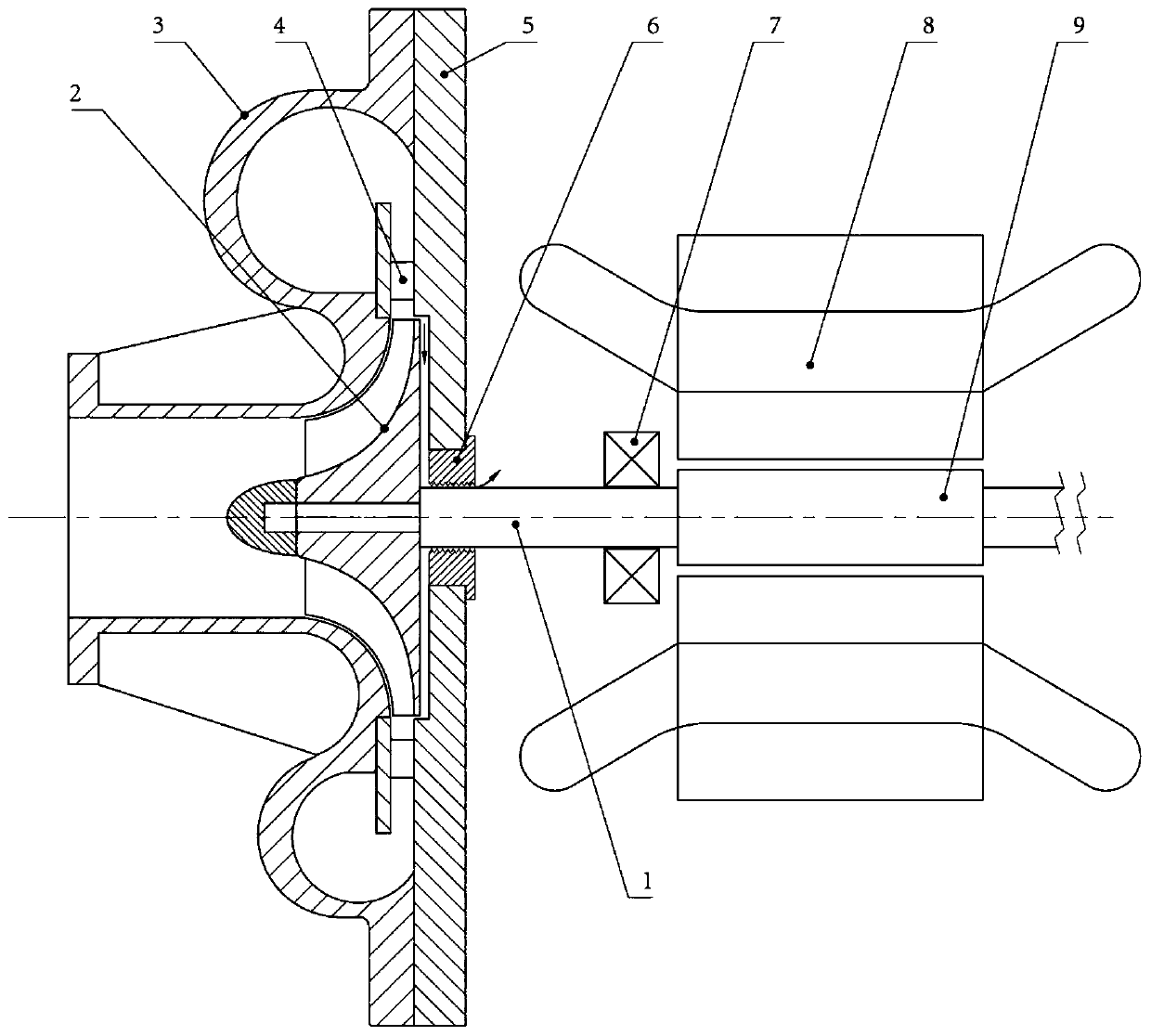
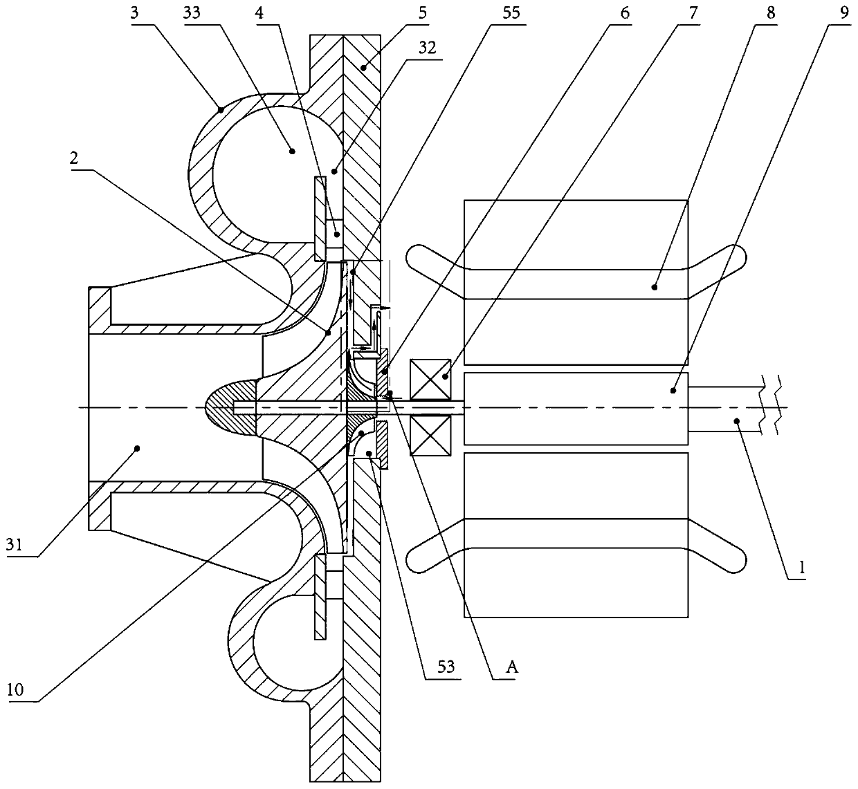
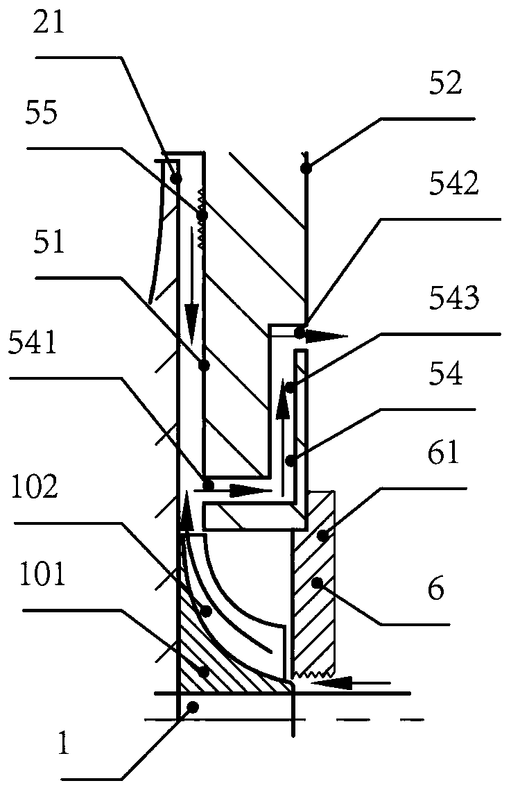
[0044] figure 2 A block diagram showing a centrifugal compressor according to a first embodiment of the present invention, image 3 show figure 2 The enlarged view of the structure in part A, Figure 4 A top view of the fin structure of the first embodiment is shown in .

[0045] Such as figure 2 and image 3 As shown, the present invention provides a centrifugal compressor, which includes a transmission shaft 1, an impeller 2, a volute 3, a diffuser 4, a back casing 5, a shaft seal 6, a bearing 7, a vane structure 10 and a high-speed motor.

[0046] The transmission shaft 1 passes through the through hole 53 opened in the center of the rear case 5 , and a shaft seal 6 such as a labyrinth seal is provided between the transmission shaft 1 and the rear case 5 . The other end of the shaft seal 6 has a flange portion 61 protruding radially outward over the entire c...

no. 2 approach

[0069] Combine below Figure 5-Figure 6 A second embodiment of the present invention will be described.

[0070] Figure 5 A block diagram of a centrifugal compressor according to a second embodiment of the present invention is shown in . Figure 6 A top view of the fin structure of the second embodiment is shown in .

[0071] In the second embodiment of the present invention, it is the same as the first embodiment except for the location where the fin structure 10' is installed and the shape and size are adjusted to suit the location. The same code|symbol is attached|subjected to the same part as 1st Embodiment.

[0072] In the second embodiment, the vane structure 10' is provided on the surface of the impeller 2 opposite to the first wall surface 51. The fin structure 10' includes a mounting plate 101' and a fin 102'. The center of the mounting plate 101' has a through hole 103' through which the transmission shaft 1 passes. The mounting plate 101' is installed on the ...

no. 3 approach

[0076] Combine below Figure 7-Figure 8 A third embodiment of the present invention will be described.

[0077] Figure 7 shows a configuration diagram of a centrifugal compressor according to a third embodiment of the present invention, Figure 8 A top view of an airfoil structure of a third embodiment is shown in .

[0078] The third embodiment of the present invention is the same as the first embodiment except for the location and shape of the fin structure 10 ″ and the shaft seal 6 ″. The same code|symbol is attached|subjected to the same part as 1st Embodiment.

[0079] In the third embodiment, the shaft seal 6" only needs to block most of the gap between the back casing 5 and the transmission shaft 1, and there is a seal between the shaft seal 6" and the transmission shaft 1 that is the same as that of the first embodiment. way and the larger gap compared to the second embodiment. The fin structure 10" is arranged on the part of the transmission shaft 1 opposite to ...


PUM


Abstract

The invention relates to a centrifugal compressor and an air blower driven by a high-speed motor. The problems that in a centrifugal compressor, leaking compressed gas at high temperature of 100 DEG C-170 DEG C from the back face of an impeller of the centrifugal compressor can heat bearings, so that the temperature exceeds the heat-resistance temperature of the bearings exist formerly. Thus, thescheme that the bearings are away from the impeller is adopted formerly. As a result, a rotor is overall lengthened, the critical rotating speed of the rotor is reduced, the rotor cannot operate at high speed, and sufficient output pressure cannot be obtained. In order to solve the problems, the following scheme is adopted, a wing structure is arranged, gas is supplied through the wing structure,and the gas reversely flows at the position of a shaft seal. Thus, leakage from the shaft seal is avoided, and the situation that the leaking gas heats the bearings is avoided. Finally the following effects that the rotor is shortened, the critical speed is increased, the operating rotating speed is increased, thus, the operating pressure is increased, and sufficient output pressure can be obtained are achieved.

Description

technical field [0001] The present invention relates to a centrifugal compressor and blower driven by a high speed motor. Background technique [0002] Centrifugal compressors are used as power sources and air sources in manufacturing plants. In order to increase the rotational speed of the impeller of the centrifugal compressor, a gear speed increaser has conventionally been used. In recent years, high-speed motors have appeared, and high-speed motors have been developed to directly drive centrifugal compressors (blowers). [0003] figure 1 A structure of a centrifugal compressor directly driven by a high-speed motor in the prior art is shown. Such as figure 1 As shown, the centrifugal compressor includes a transmission shaft 1 , an impeller 2 , a volute 3 , a diffuser 4 , a back casing 5 , a shaft seal 6 , a bearing 7 , a stator 8 and a rotor 9 . The transmission shaft 1 penetrates through the through hole of the rear case 5 , and a shaft seal 6 such as a labyrinth se...

Claims


Application Information

Patent Timeline
Patent Type & Authority Applications(China)
IPC IPC(8): F04D17/10F04D17/08F04D25/06F04D29/00F04D29/28F04D29/10
CPCF04D17/08F04D17/10F04D25/06F04D29/002F04D29/102F04D29/281F04D29/284
Inventor 长谷川和三鲁寅
Owner SHANGHAI HANBELL PRECISE MASCH CO LTD
Why Eureka
Try Eureka