Shaft seal structure of low temperature pump and sealing gas control system of shaft seal

A cryogenic pump and shaft seal technology, which is applied to the components, pumps, and pump components of the pumping device for elastic fluids, which can solve the problems of unreliable sealing, small molecular weight, easy leakage, etc. , reasonable structure, easy to use effect

Active Publication Date: 2014-07-30
HANGZHOU HANGYANG KOSO PUMP & VALVE
View PDF5 Cites 0 Cited by
  • Summary
  • Abstract
  • Description
  • Claims
  • Application Information

AI Technical Summary

Problems solved by technology

[0002] In the existing cryogenic medium circulation process, the cryogenic pump is required to run continuously without interruption, and at the same time, the purity of the conveying medium is not affected; usually, the shaft seal type of the cryogenic pump is: mechanical seal and stuffing seal at low temperature (-196°C) only It can be used intermittently and cannot meet the long-term continuous requirements, and the non-metallic material of the mechanical seal and packing seal will enter the medium delivered by the cryogenic pump after wear and tear, thereby affecting the purity of the delivery medium. Because the low temperature medium is easy to gasify and has a small molecular weight, It is easy to leak, so the usual non-inflatable labyrinth seal cannot be reliably sealed, especially when the inlet pressure of the cryopump fluctuates, it is even more difficult to achieve a reliable seal

Method used


Image

  • Shaft seal structure of low temperature pump and sealing gas control system of shaft seal
  • Shaft seal structure of low temperature pump and sealing gas control system of shaft seal

Examples


Embodiment Construction

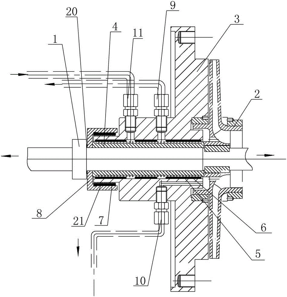
[0012] The present invention will be described in detail below in conjunction with accompanying drawing: figure 1 As shown, the shaft seal structure of the cryopump according to the present invention includes a seal seat 3 which is sleeved on the pump shaft 1 through a shaft hole and is closely attached to the pump body 2, and the seal seat 3 and the pump shaft 1 There is a labyrinth 4 and a first sealing lining 5 which is located outside the labyrinth 4 and is embedded in the shaft hole of the sealing seat. A labyrinth seal pair 6 is formed in cooperation with the seal grooves that run out of the structure due to mutual rotation and running-in; the outer end of the seal seat 3 is provided with a sleeve-type retaining ring 8 with a second seal lining 7; 3 are respectively provided with three air source interfaces communicating with the labyrinth-shaped sealing pair 6, and the three air source interfaces are respectively connected to the mixing air pipe joint 9, the labyrinth u...


PUM


Abstract

The invention discloses a shaft seal structure of a low temperature pump and a sealing gas control system of a shaft seal. The shaft seal structure of the low temperature pump comprises a sealing seat, wherein a labyrinth sleeve and a first sealing liner are arranged between the sealing seat and a pump shaft, the first sealing liner is positioned outside the labyrinth sleeve and is embedded in a shaft hole of the sealing seat, and a labyrinth type sealing pair is formed in a way that a comb-tooth structure arranged on the labyrinth sleeve is matched with a sealing groove, which runs out of the first sealing liner, on the first sealing liner due to mutual rotational running of the comb-tooth structure and the first sealing liner; the outer end of the sealing seat is provided with a shaft sleeve type check ring with a second sealing liner; the sealing seat is respectively provided with three air source connectors which are communicated with the labyrinth type sealing pair. According to the shaft seal structure disclosed by the invention, the low temperature pump can be used in a process technology which is capable of meeting continuous running and does not affect the medium purity, and the reliable running of the low temperature pump cannot be affected by the pressure fluctuation at an inlet of the low temperature pump.

Description

technical field [0001] The invention relates to a shaft seal structure of a low temperature pump and a shaft seal air control system, belonging to low temperature mechanical equipment. Background technique [0002] In the existing cryogenic medium circulation process, the cryogenic pump is required to run continuously without interruption, and the purity of the conveying medium is not affected; usually, the shaft seal type of the cryogenic pump is: mechanical seal and stuffing seal at low temperature (-196°C) only It can be used intermittently and cannot meet the long-term continuous requirements, and the non-metallic material of the mechanical seal and packing seal will enter the medium delivered by the cryogenic pump after wear and tear, thereby affecting the purity of the delivery medium. Because the low temperature medium is easy to gasify and has a small molecular weight, It is easy to leak, so the usual non-inflatable labyrinth seal cannot be reliably sealed, espec...

Claims


Application Information

Patent Timeline
IPC IPC(8): F04D29/10
Inventor 胡赟王维博
Owner HANGZHOU HANGYANG KOSO PUMP & VALVE
Why Eureka
Try Eureka