Optical axis calibration gauge, system and method

A calibration method and optical axis technology, applied in the direction of testing optical performance, etc., can solve the problems of complex structure and high cost of optical axis calibration fixture, and achieve the effect of convenient optical axis calibration method, simple structure and cost reduction.

Active Publication Date: 2014-07-30
QINGDAO GOERTEK
View PDF11 Cites 18 Cited by
  • Summary
  • Abstract
  • Description
  • Claims
  • Application Information

AI Technical Summary

Problems solved by technology

[0006] In order to solve the problems of complex structure and high cost of the existing optical axis alignment jig

Method used


Image

  • Optical axis calibration gauge, system and method
  • Optical axis calibration gauge, system and method
  • Optical axis calibration gauge, system and method

Examples


Embodiment 1

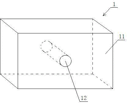
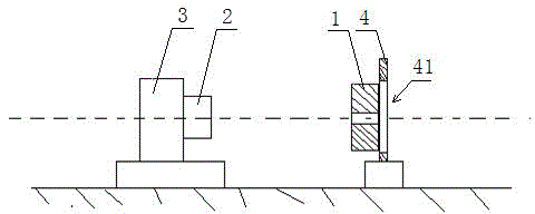
[0040] Embodiment 1, this embodiment provides an optical axis calibration jig, see figure 2 As shown, the optical axis calibration jig 1 includes a body 11. In order to clearly introduce the working principle of the present invention, in this embodiment, the body 11 is provided with a circular through hole 12, and the through hole 12 is two ends Straight holes parallel to each other, see image 3 shown, the via length , where h is the length of one pixel of the calibration camera, It is the maximum deviation angle value of the fixture. By accurately calculating and limiting the length of the through hole, the optical axis calibration jig can not only limit the deviation within the required accuracy range, meet the calibration accuracy requirements, but also make the calibration accuracy of the optical axis calibration jig not too large ( The larger the L, The smaller the value, the higher the corresponding accuracy), which is beneficial to reduce the amount of calculat...

Embodiment 2

[0045] Embodiment 2, based on the optical axis calibration system in Embodiment 1, this embodiment provides an optical axis calibration method, including the following steps:

[0046] (1) Make the optical axis calibration jig, please refer to the attached drawings Figure 2-Figure 4 shown, including: Computing the length value , where h is the length of one pixel of a calibration camera, In order to calibrate the maximum deviation angle value of the fixture; according to the length value L, the optical axis calibration fixture 1 is made, and the optical axis calibration fixture 1 includes a body 11, and a circular or polygonal through hole 12 is opened on the body, and the through hole is A straight hole with two ends parallel to each other, and the length of the through hole is L;

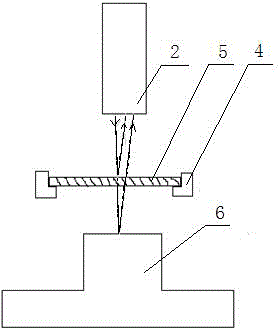
[0047] (2) Fix the optical axis calibration jig 1 on a carrying platform 4, the carrying platform 4 has a light transmission hole 41, the light transmission hole 41 is connected with the throu...


PUM


Abstract

The invention discloses an optical axis calibration gauge, system and method. The optical axis calibration gauge comprises a gauge body, wherein a round through hole is formed in the gauge body; the through hole is a straight hole of which the two end faces are parallel; the length L of the through hole is h/tan theta, wherein h is the length of one pixel of a calibrated camera, and theta is the maximum deviation angle value of the gauge. The optical axis calibration gauge can limit the deviation within the precision range required by tested products, the calibration precision requirement is met, the calibration precision of the calibration gauge is not too large, the calculated amount for calibration is reduced, the structure is simple, and the cost of optical axis calibration equipment is lowered greatly.

Description

technical field [0001] The invention belongs to the technical field of optical axis calibration, and in particular relates to an optical axis calibration fixture, system and method. Background technique [0002] In the calibration of various optical equipment or fixtures, the calibration accuracy of the optical axis will directly affect the accuracy of the equipment, which is one of the important tasks of equipment debuggers. [0003] At present, the method of three points and one line is generally used to calibrate the straight line, but it is more difficult to calibrate the optical axis. Some high-precision instruments must be used for detection, or lasers, autocollimators, etc. are used. [0004] Such as figure 1 As shown, it is the optical axis calibration principle of the autocollimator. The calibration camera 2 emits a beam of light through the flat glass 5, part of the light is reflected back to the calibration camera 2, and part of the light passes through the flat ...

Claims


Application Information

Patent Timeline
IPC IPC(8): G01M11/02
Inventor 赵博刚杨春周宏伟
Owner QINGDAO GOERTEK
Why Eureka
Try Eureka