
System and method for testing high-frequency fatigue life in high-temperature steam environment

A high-temperature steam and fatigue life technology, applied in the direction of applying repetitive force/pulse force to test the strength of materials, etc., can solve the problem of not being able to meet the high-temperature steam environment, and achieve the effect of easy guarantee of test accuracy, simple operation and good sealing.

Inactive Publication Date: 2014-07-30
EAST CHINA UNIV OF SCI & TECH
View PDF3 Cites 20 Cited by
  • Summary
  • Abstract
  • Description
  • Claims
  • Application Information

AI Technical Summary

Problems solved by technology

The conventional corrosion fatigue testing machine is not equipped with a high-temperature steam generating device and its circulation system. There are existing Chinese patents "An Environmental Device for Fatigue Crack Growth Rate Test in a Corrosion Environment" (Application No.: 200810167021.7) Fatigue test system" (application number: 201310360438.6), "a salt spray environment device for fatigue performance test" and "corrosion fatigue test device with high temperature and high pressure circulating water" (application number: 200920270850.8), etc. are provided A solution environment device for carrying out fatigue tests, but it cannot meet the requirements of high temperature steam environment
In addition, in the service environment of the blade, the oxygen content in the wet steam is generally lower than 1 ppm, which poses a new challenge to the development of the steam fatigue test system

Method used


Image

  • System and method for testing high-frequency fatigue life in high-temperature steam environment
  • System and method for testing high-frequency fatigue life in high-temperature steam environment
  • System and method for testing high-frequency fatigue life in high-temperature steam environment

Examples


Embodiment Construction

[0057]The specific implementation of the high-frequency fatigue life test system and test method in the high-temperature steam environment of the present invention will be described in detail below in conjunction with the accompanying drawings. The implementation object of this example is the steam turbine blade material Ti-6Al-4V, its service environment is steam at 100oC, and the dissolved oxygen content is required to be less than 0.8ppm.

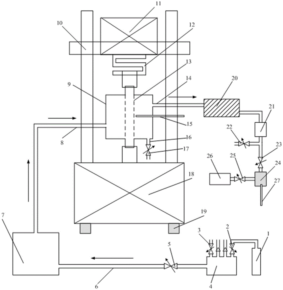
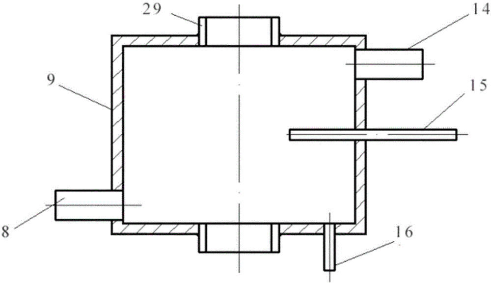
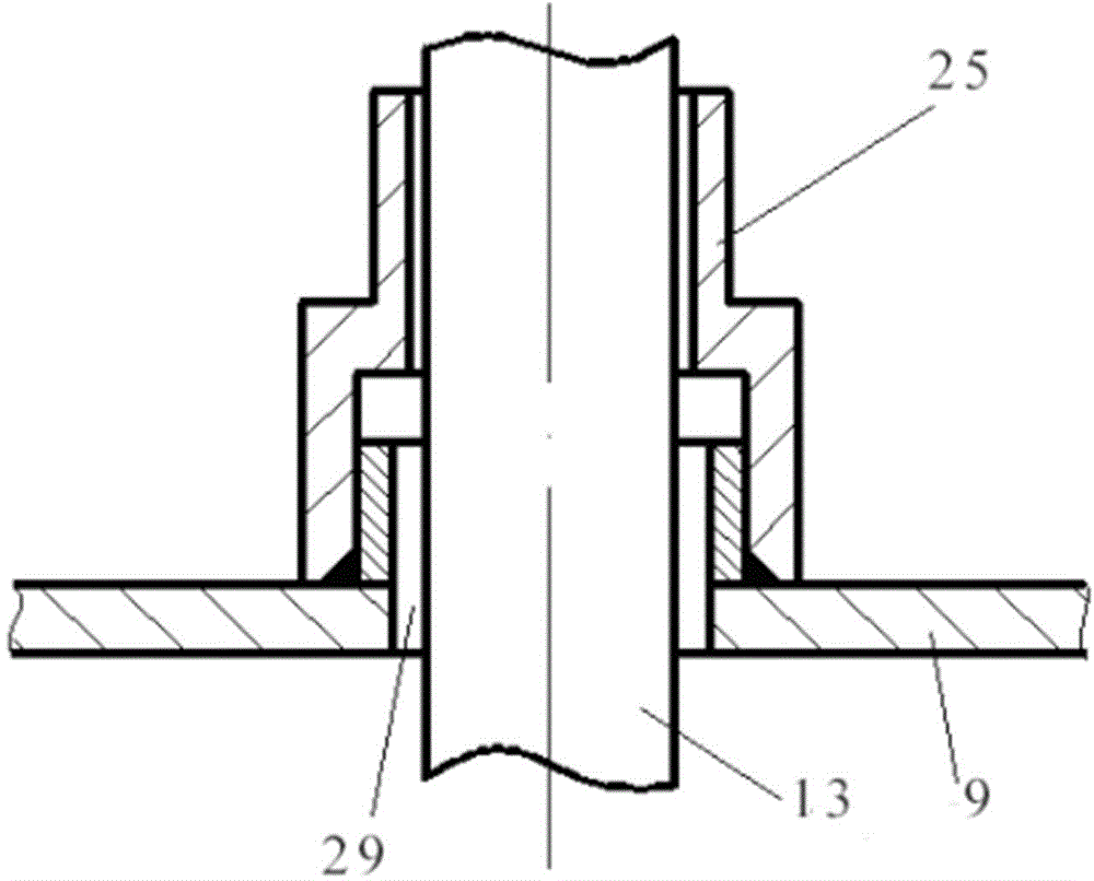
[0058] See attached figure 1 , the high-frequency fatigue life test system includes the vibration excitation device 11 of the fatigue testing machine, the load transfer device 12 and the steam box 9, the steam box 9 is used for the high-temperature steam service environment of the material, the vibration excitation device 11 of the fatigue testing machine, the load transfer device 12 and the steam box 9 are installed on the test frame 10, the load transmission device 12 realizes the cyclic loading of the sample 13, the sample 13 passes t...


PUM


Abstract

The invention belongs to the technical field of material performance tests and discloses a system for testing high-frequency fatigue life in a high-temperature steam environment. The system comprises a test rack, wherein a steam box and a fatigue testing machine are fixedly arranged on the test rack; high-frequency cyclic loading of a fatigue sample is realized through the fatigue testing machine; the sample penetrates through the steam box; two ends of the sample are respectively and rotatably connected with the steam box in a sealed mode; a middle part of the sample is exposed in an internal environment of the steam box; the steam box comprises a steam input end and a steam output end; the steam input end of the steam box is connected with a steam generator; the steam generator is supplied with water by a water tank; an oxygen removal device is arranged on the water tank; the steam output end of the steam box is connected with a condenser; an oxygen content measuring device is connected to the condenser. The invention also discloses a related test method. The adopted steam generator can generate water vapor with stable flow. By arranging a dissolved oxygen testing device and monitoring steam temperature in real time, an operating environment of an actual member can be simulated to the greatest degree.

Description

technical field [0001] The invention belongs to the technical field of material performance testing, in particular to a high-frequency fatigue life testing system and testing method in a high-temperature steam environment. Background technique [0002] As the core component of electric power equipment, steam turbine's design and manufacturing level reflect the strength of technological innovation. The blades of steam turbines are energy and power components, and their safety and reliability are directly related to the long-term stable operation of power plant units. For example, in the final blade area, the diameter and rotational speed are large, the centrifugal force and alternating stress act together, the working load is complex, and it works in a wet steam environment. The complex working conditions and harsh service environment of steam turbine blades can easily cause fatigue damage. The design of the blade and its structure, the selection of blade materials and othe...

Claims


Application Information

Patent Timeline
IPC IPC(8): G01N3/38
Inventor 轩福贞朱明亮李煜佳涂善东
Owner EAST CHINA UNIV OF SCI & TECH
Learn More