Method for measuring diode transient temperature rise in real time

A technology of transient temperature rise and real-time measurement, applied in the direction of single semiconductor device testing, etc., can solve the problem of inapplicability of transient temperature rise measurement of devices, and achieve the goal of avoiding the influence of temperature rise, eliminating temperature rise error and improving test accuracy Effect

Inactive Publication Date: 2014-07-30
BEIJING UNIV OF TECH
View PDF3 Cites 14 Cited by
  • Summary
  • Abstract
  • Description
  • Claims
  • Application Information

AI Technical Summary

Problems solved by technology

There will be a time delay during the switching process of the working current and the test current. Experiments have shown that a time delay of 1us may cause a temperature change of more than 200°C
However, the switching speed of the device itself is relatively fast, and the delay time of the current equipment is generally 1-10us, which is not suitable for the measurement of the transient temperature rise of the device under the pulse working condition.

Method used


Image

  • Method for measuring diode transient temperature rise in real time
  • Method for measuring diode transient temperature rise in real time
  • Method for measuring diode transient temperature rise in real time

Examples


Embodiment Construction

[0025] The present invention will be described in more detail below in conjunction with the accompanying drawings and specific embodiments.

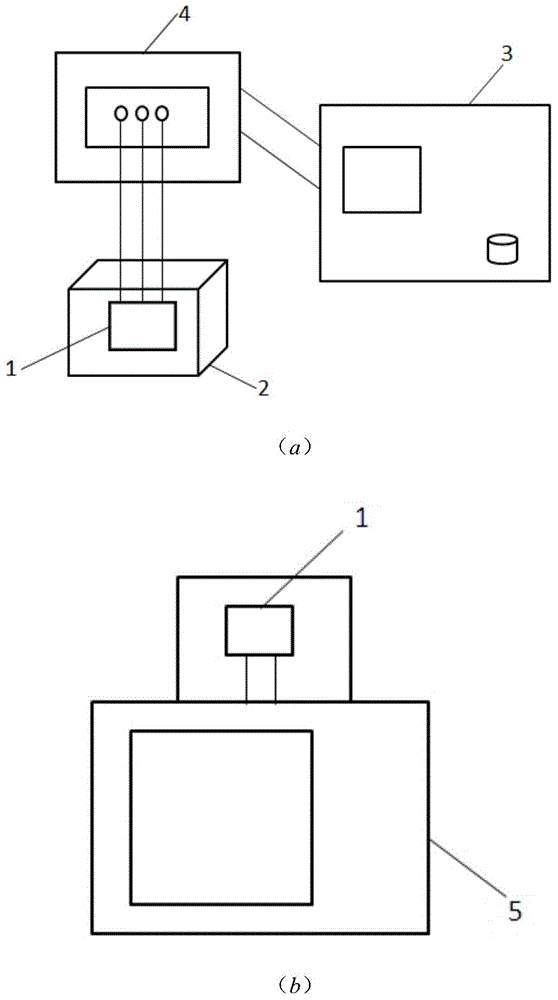
[0026] The testing device involved in the present invention is as figure 1 (a) and (b) shown. It includes a diode 1, a thermostat 2, a graph instrument 3, a device fixture 4 and a semiconductor parameter analyzer 5. Diode 1 is a fast recovery diode, packaged in TO-247-2L type, with a maximum forward voltage of 3.1V and a maximum forward current of 30A. The tracer 3 adopts the Agilent 371A high-power curve tracing instrument. Thermostat 2 uses Despatch900series. Semiconductor parameter analyzer 5 adopts Agilent B1500 precision semiconductor parameter analyzer.

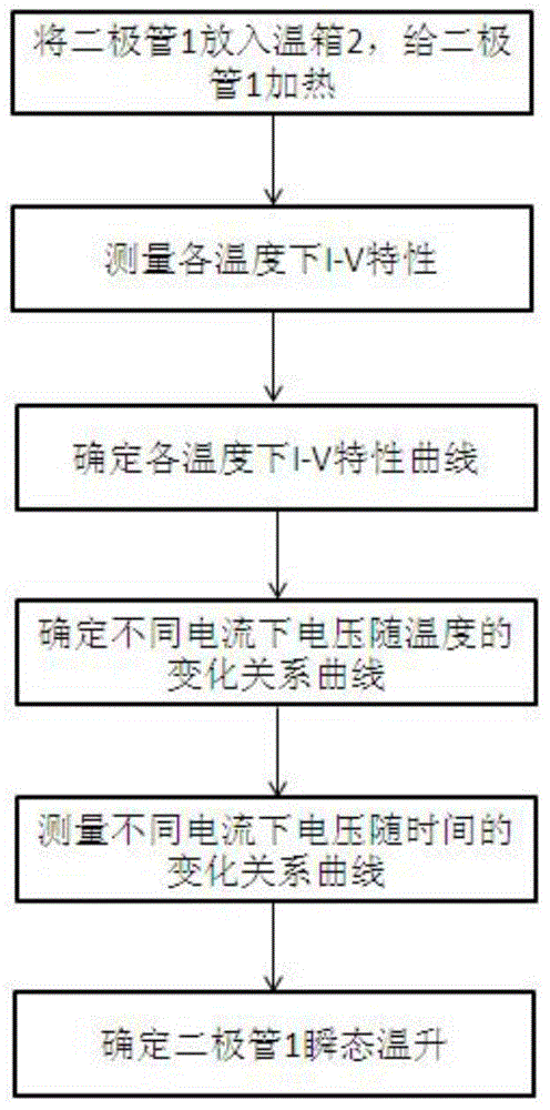
[0027] The flowchart of the method involved in the present invention is as figure 2 shown, including the following steps:

[0028] Step 1, connect the diode 1 with the device fixture 4 of the graph instrument 3 through wires, put the diode 1 into the incubator, and use the ...


PUM


Abstract

The invention relates to a method for measuring the diode transient temperature rise in real time. The method includes the steps of firstly conducting I-V characteristic measurement on a measured diode at different temperatures to obtain an I-V characteristic curve, wherein electric currents applied to the diode are narrow pulse electric currents, and the self temperature rise of the diode can be avoided; then obtaining a curve of the relation between voltages under different electric currents and temperature changes according to the I-V characteristic curve; then collecting a relation, between the voltages under different electric currents and time changes, of the diode through semiconductor parameter analysis meters; finally obtaining the diode transient temperature rise in cooperation with the prior-obtained curve of the relation between the voltages under the different electric currents and the temperature changes. By means of the method, a switch-free measuring device is adopted for measuring the diode transient temperature rise in real time; compared with an existing measurement method related to a switching device with a switch, temperature rise errors caused by switching delaying are eliminated. Meanwhile, the narrow pulse electric currents generated by graphic instruments are small enough in pulse width, influences of the diode self temperature rise on the temperature rise can be effectively avoided, and the measurement accuracy is greatly improved.

Description

technical field [0001] The invention belongs to the field of electronic device testing and relates to a method for measuring and analyzing the transient temperature rise of a diode. technical background [0002] At present, semiconductor devices are constantly developing in the direction of small size and high integration. At the same time, power diodes need to work under different high-current voltage pulses or switching conditions. The transient power density of the device is high, and the transient temperature rises, resulting in a decrease in device characteristics, reduced reliability, and shortened life. In order to accurately evaluate its reliability, it is particularly important to accurately measure the transient temperature rise of the device. [0003] The transient temperature rise test of diodes mostly adopts the electrical method. The relevant standards mainly include the national military standard 128A-973103, the US military standard MIL-STD-750E3101.4, etc.,...

Claims


Application Information

Patent Timeline
Patent Type & Authority Applications(China)
IPC IPC(8): G01R31/26
Inventor 郭春生王琳冯士维李睿张燕峰李世伟
Owner BEIJING UNIV OF TECH
Why Eureka
Try Eureka