Spectrum broadening and recompression in high-energy fiber laser system

a fiber laser and high-energy technology, applied in the direction of laser details, basic electric elements, electrical apparatus, etc., can solve the problems of limited cpa systems, limited cpa systems, and limitations that were not addressed in conventional technologies, so as to improve the controllability of pulse generation processes.

Inactive Publication Date: 2007-03-01
POLARONYX
View PDF4 Cites 11 Cited by
  • Summary
  • Abstract
  • Description
  • Claims
  • Application Information

AI Technical Summary

Benefits of technology

[0013] In a preferred embodiment, this invention further discloses a method for overcoming the drawback in a fiber CPA laser system. The method includes a step of generating a nonlinear phase shift after the pulse is amplified to compensate and reduce the TOD. In a preferred embodiment, the method further includes a step of shaping the pulse right after the pulses are amplified to further improve the controllability of the pulse generation processes.

Problems solved by technology

Even though current technologies of fiber laser have made significant progress toward achieving a compact and reliable fiber laser system providing high quality output laser with ever increasing output energy, however those of ordinary skill in the art are still confronted with technical limitations and difficulties.
Specifically, in a fiber laser system implemented with the Chirped Pulse Amplification (CPA) for short pulse high power laser amplifier, the CPA systems are still limited by the technical difficulties that the third order dispersion (TOD) limits the scalability of the laser systems.
Such limitations were not addressed in the conventional technologies due to the fact that the conventional solid-state laser utilizes Grating-Lens combination and Treacy compressor for pulse stretching and compressing.
Ideally, in such solid-state systems, all orders of dispersion can be compensated, but the material dispersion can distort and damage this ideal situation.
However, for a fiber laser system, the situation is different due to the fact that in the fiber laser systems, attempts are made by using the fiber stretcher to replace the grating-lens combination for the purpose of significantly increasing the system reliability.
However, the TOD limits the ability for de-chirping when using Treacy compressor since both fiber stretcher and Treacy compressor have positive TOD even this combination can remove the second order dispersion completely.
This issue of TOD dispersion makes it more difficult to develop a high-energy fiber laser amplifier with <200 fs pulse width.
Actually, the technical difficulty of TOD dispersion is even more pronounced for laser system of higher energy.
Therefore, for laser system of higher energy, it is even more difficult to re-compress the pulse to the original pulse width.
However, the issue of generating a short pulse width in a fiber laser system is always difficult to achieve due to an uncompensated highly positive third-order dispersion (TOD) generally referred to as the compressibility issue.
However, in practice, this conventional dogmatic design concept is no longer considered as universally acceptable.
The concept of applying the phase shift and spectral generation for improvement of pulse quality as that disclosed in a fiber Raman amplifier does not provide a direct solution to the difficulties caused by the compressibility issues due to the technical challenges arise from the third order dispersion effects.

Method used


Image

  • Spectrum broadening and recompression in high-energy fiber laser system
  • Spectrum broadening and recompression in high-energy fiber laser system
  • Spectrum broadening and recompression in high-energy fiber laser system

Examples


Embodiment Construction

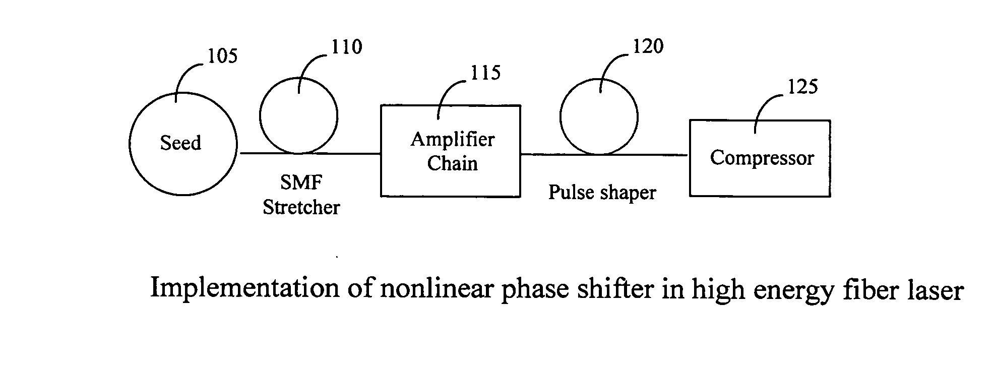
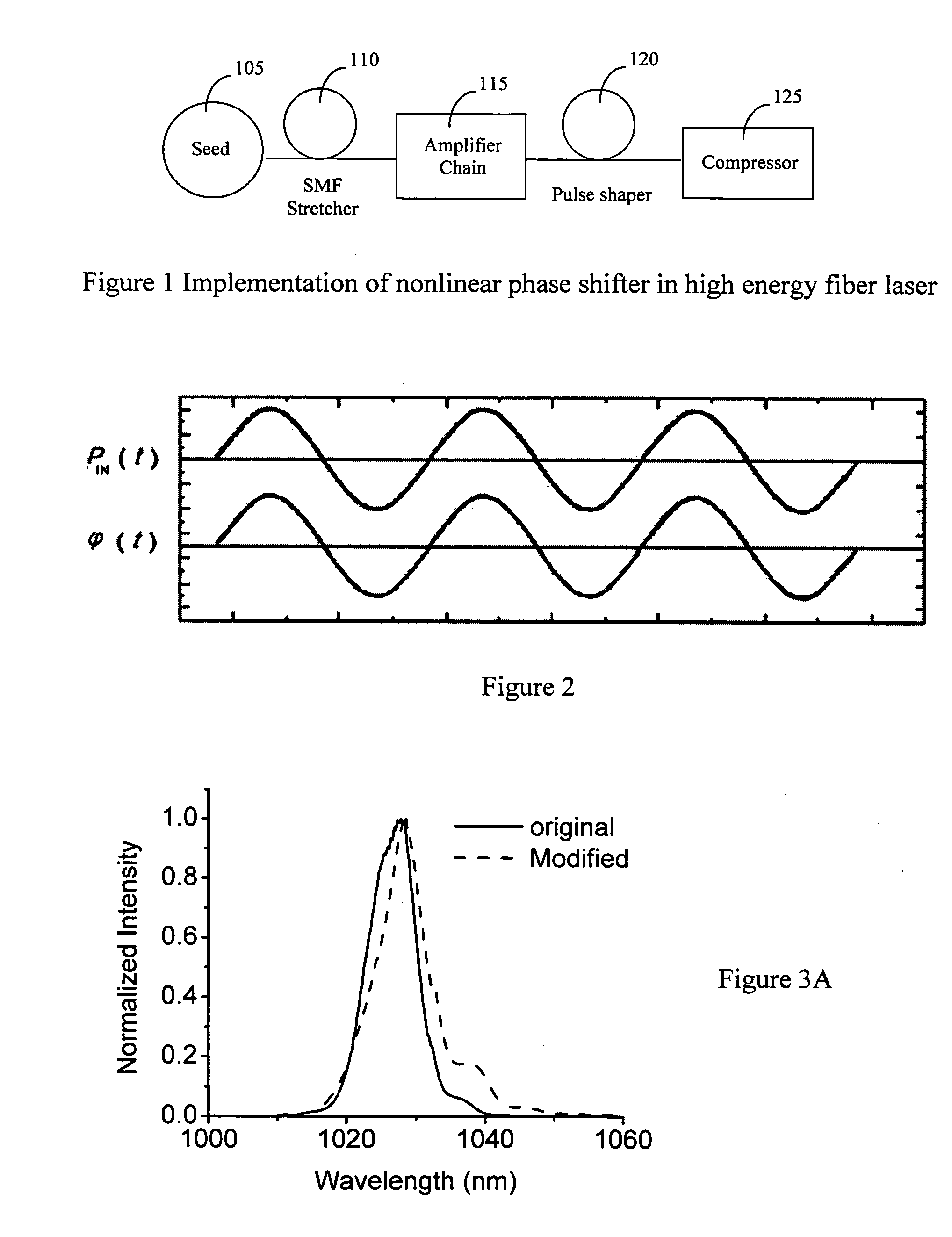
[0019] Referring to FIG. 1 for a schematic diagram of a fiber laser system 100 of this invention that implements a dispersion compensator of this invention. The laser system 100 includes a laser seed 105 for generating a seed laser for projecting into a laser stretcher 110 to stretch the laser pulse. The stretcher 110 generates laser pulse with stretched pulse width is projected into a series of laser amplifiers 115 to amplify the laser into higher energy. The amplified laser is then projected into a pulse shaper 120 as a newly added device to the fiber laser system this invention. The pulse-shaped signals are then projected to a compressor 125. The compressor is now implemented with a nonlinear phase generator to generate nonlinear phase shift to compensate and reduce the TOD dispersions and in the meantime recompress the stretched pulse into the original pulse width.

[0020] By implementing a nonlinear phase generation in the compressor 125 after the high-energy amplifier to compen...


PUM


Abstract

A fiber Chirped Pulse Amplification (CPA) laser system includes a fiber mode-locking oscillator for generating a laser for projecting to a fiber stretcher for stretching a pulse width of the laser. The fiber CPA laser further includes a multistage amplifier for amplifying the laser for projecting into a pulse shaper then to a compressor having a nonlinear phase generator for compensating high order dispersions and compressing the pulse width of the laser. The pulse shaper is further provided to minimize a nonlinear phase shift inside the multistage amplifier for reducing a Stimulated Raman Scattering (SRS

Description

[0001] This Formal Application claims a Priority Date of Aug. 29, 2005 benefited from a Provisional Patent Application 60 / 713,650, 60 / 713,653, and 60 / 713,654 and a Priority Date of Sep. 1, 2005 benefited from Provisional Application 60 / 714,468 and 60 / 714,570 filed by one of the same Applicants of this Application.FIELD OF THE INVENTION [0002] The present invention relates generally to apparatuses and methods for providing fiber laser system. More particularly, this invention relates a system configuration for spectrum broadening and pulse width recompression for correcting the third order dispersions (TOD) in a Chirped Pulse Amplification (CPA) fiber laser system. BACKGROUND OF THE INVENTION [0003] Even though current technologies of fiber laser have made significant progress toward achieving a compact and reliable fiber laser system providing high quality output laser with ever increasing output energy, however those of ordinary skill in the art are still confronted with technical ...

Claims


Application Information

Patent Timeline
Patent Type & Authority Applications(United States)
IPC IPC(8): H01S3/30H01S3/098
CPCH01S3/0057H01S3/06758H01S3/06725H01S3/067
Inventor LIU, JIANXIA, JIANGFAN
Owner POLARONYX
Why Eureka
Try Eureka