Solar energy and wind energy generation combined device

A power generation device and combined device technology, applied in the field of solar and wind power generation, can solve the problems of high foundation requirements, complex structure, high technical content, etc.

Active Publication Date: 2014-07-30
许润柱
View PDF6 Cites 14 Cited by
  • Summary
  • Abstract
  • Description
  • Claims
  • Application Information

AI Technical Summary

Problems solved by technology

[0002] The electric energy used by road lighting lamps is generally provided by thermal power plants and hydropower plants. Solar power and wind power are rarely used, and more photovoltaic solar panels are used. The solar panels are fixed on poles, or Computers are used to control the expensive anti-Japanese system; horizontal-axis windmills use wind energy, which has high technical content, complex structures, and high requirements for foundations, and vertical-axis windmills will also be affected by headwinds. Although there are cases where deflectors are used, Nor is it free from headwinds

Method used


Image

  • Solar energy and wind energy generation combined device
  • Solar energy and wind energy generation combined device
  • Solar energy and wind energy generation combined device

Examples


Embodiment Construction

[0019] Case number one,

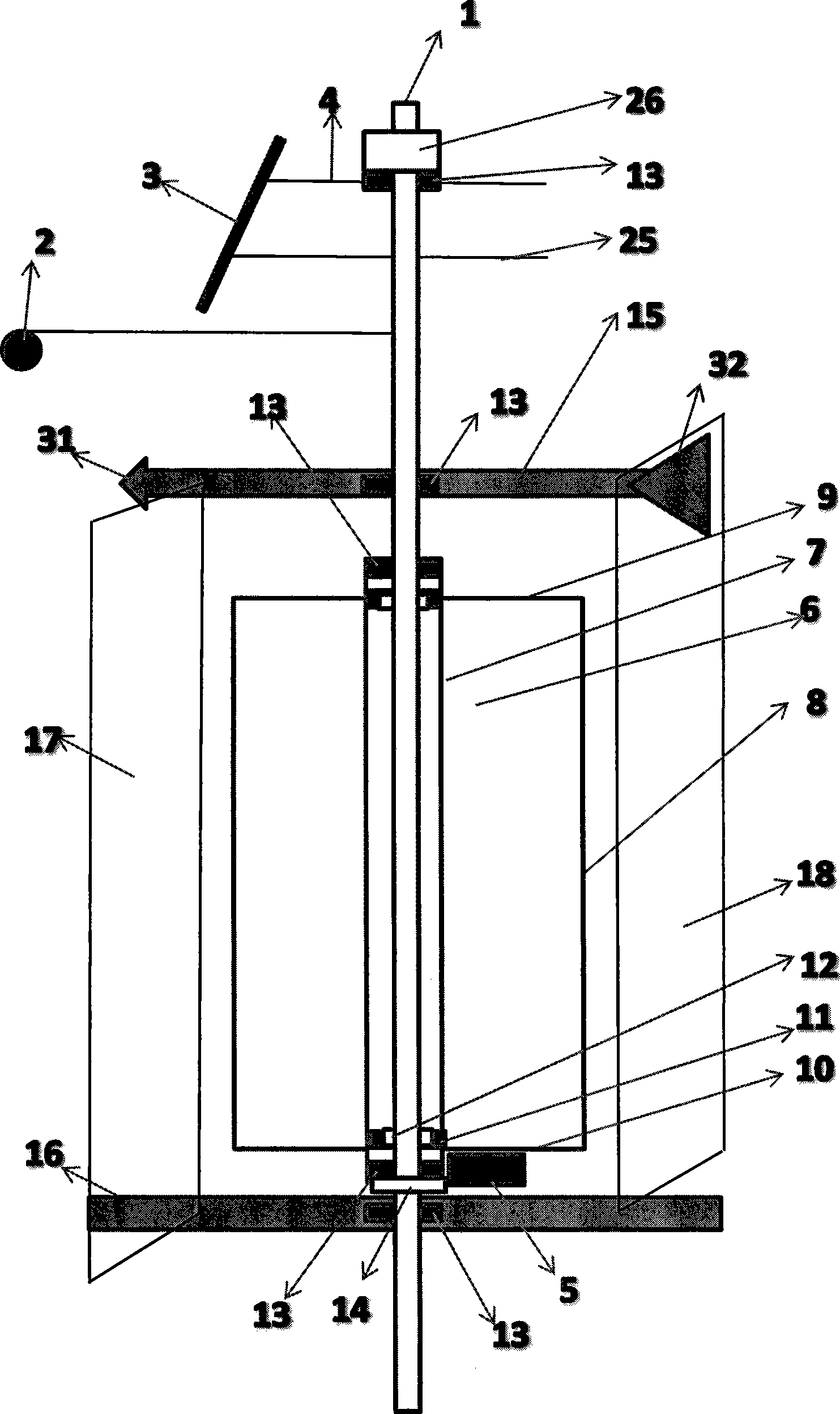
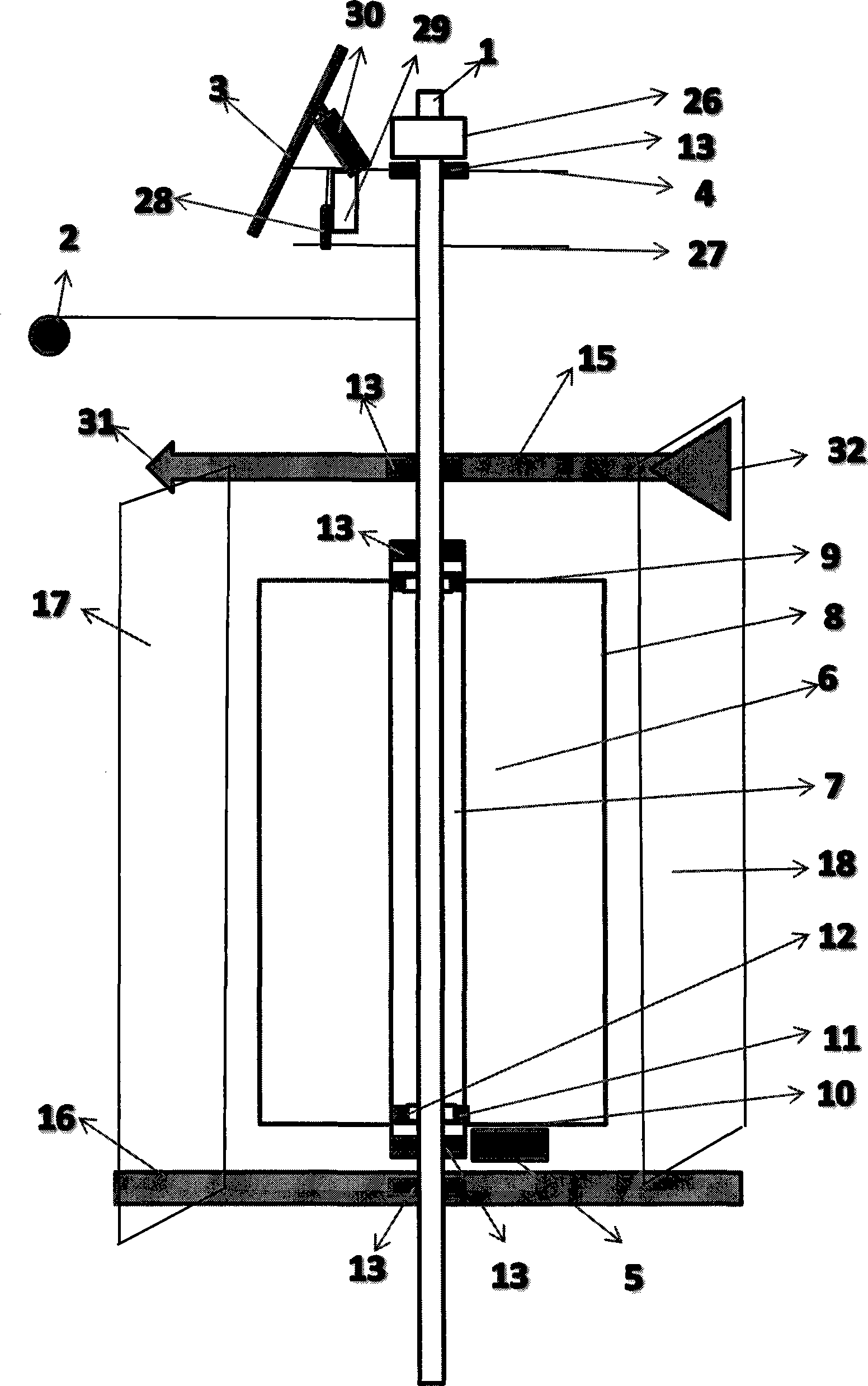
[0020] On the lamp 2 of the pole 1, the transmission device 4, the cam ring rolling device 25 and the motor 26 that move horizontally around the center and move up and down according to the sun-aligning track are fixed on the pole 1, and the power drives the solar panel 3 according to the sun-aligning The track moves horizontally around the center and the transmission combination device 4 that moves up and down directs the dish concentrator power generation device or photovoltaic panel power generation device 3 towards the zero-degree east in the morning. The upper side of the solar panel 3 is connected to the horizontal moving device 4, and the lower side is connected to the cam. Sliding on the ring rolling device 25, clockwise from zero degrees according to the law of time while panning and tilting, reaching 90 degrees at noon in the south while panning and tilting according to the law of time, and stopping at 180 degrees west in the evening. The la...


PUM


Abstract

The invention discloses a solar energy and wind energy generation combined device. Wind energy or electric energy is used as power, a disc condenser generation device or a photovoltaic cell panel generation device on a vertical rod for road lighting is moved towards the east in the morning, and starting from the zero-degree position in the east in the clockwise direction, the disc condenser generation device or the photovoltaic cell panel generation device is simultaneously moved horizontally and ascends according to the track of the sun along with the rule of time; when reaching the ninety-degree position in the south at the noon, the disc condenser generation device or the photovoltaic cell panel generation device is simultaneously moved horizontally and starts to descend along with the rule of time; when reaching the position of one hundred and eighty degrees in the west in the afternoon, the disc condenser generation device or the photovoltaic cell panel generation device stops descending and continues to be moved horizontally along with the rule of time; when moved horizontally to the position of three hundred and sixty degrees in the east, the disc condenser generation device or the photovoltaic cell panel generation device starts to be simultaneously moved horizontally and ascends clockwise, and the disc condenser generation device or the photovoltaic cell panel generation device circulates according to the rule by a cycle per day or returns to the zero-degree position in the morning from the position of the one hundred and eighty degrees to start circulation. The invention discloses a vertical shaft windmill. According to the windmill on the vertical rod for road lighting, the direction of a guide plate is controlled through a weather cock empennage, the guide plate rotates along with changes of the wind direction, wind guided by the guide plate is tangent to blades of a wind wheel, and the guide plate controlled by a weather cock serves as an overload protection device during the storm wind.

Description

Technical field: [0001] The device relates to the field of solar and wind power generation using natural energy. Background technique: [0002] The electric energy used by road lighting lamps is generally provided by thermal power plants and hydropower plants. Solar power and wind power are rarely used, and more photovoltaic solar panels are used. The solar panels are fixed on poles, or Computers are used to control the expensive anti-Japanese system; horizontal-axis windmills use wind energy, which has high technical content, complex structure, and high requirements for foundations, while vertical-axis windmills will also be affected by headwinds. Although there are cases where deflectors are used, Nor is it free from headwinds. Invention content: [0003] The current photovoltaic panel power generation device for road lighting is fixed on the pole at a certain inclination in one direction, and the sun moves horizontally around the center and moves up and down, so that t...

Claims


Application Information

Patent Timeline
Patent Type & Authority Applications(China)
IPC IPC(8): H02S10/12H02S20/32F03D9/02F03D3/04F03D3/06F03G6/06
CPCY02E10/46Y02E10/50Y02E10/74
Inventor 许润柱
Owner 许润柱
Why Eureka
Try Eureka