Electromagnetic interference testing method of multimode multi-standby terminal

A multi-mode multi-standby terminal, electromagnetic interference technology, applied in electrical components, transmission monitoring, transmission systems and other directions, can solve problems such as channel influence, and achieve the effect of solving the test problem of electromagnetic interference degree and receiving sensitivity

Inactive Publication Date: 2014-07-30
CHINA ACADEMY OF INFORMATION & COMM +1
View PDF1 Cites 9 Cited by
  • Summary
  • Abstract
  • Description
  • Claims
  • Application Information

AI Technical Summary

Problems solved by technology

However, when testing a certain module in a multi-mode multi-standby terminal, other modules other than the tested module will interfere with the tested module during operation, and such inter-module interference is often not full-band interference. It only affects some channels in the working frequency band of the module under test
In addition, the most disturbed channel of the module under test may not be the lowest, middle or highest channel of its operating frequency band

Method used


Image

  • Electromagnetic interference testing method of multimode multi-standby terminal
  • Electromagnetic interference testing method of multimode multi-standby terminal

Examples


Embodiment Construction

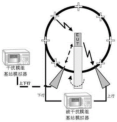
[0020] The EMI test of multi-mode terminals can be tested with the help of traditional OTA chambers. The test system is as follows: figure 1 As shown, it mainly includes measurement antennas, two sets of communication antennas, two base station simulators, and turntable systems. When testing the electromagnetic interference of module A of the terminal under test to module B, the base station simulator corresponding to module B outputs a downlink signal, which is radiated to the terminal under test through the measurement antenna, and the uplink transmission signal of module B of the terminal under test passes through a The group communication antenna is connected to the base station simulator of module B, so as to establish a test communication loop between terminal module B and its base station simulator, such as figure 1 Indicated by the solid line signal. In addition, a communication loop is established between the terminal module A under test and its base station simulato...


PUM


Abstract

An electromagnetic interference testing method of a multimode multi-standby terminal is characterized in that first, the TIS at a single-shot state of a tested module is measured first, and the spatial orientation and the polarization where the antenna receiving sensitivity is the highest are located; then on the spatial orientation and the polarization, according to a method provided at a previous stage, proper basic station downlink emitting power is set, the error probability under a multimode concurrence working state of the tested module is tested in a sweep mode, and a channel with the worst receptivity is found; finally the TIS performance of the worst channel under the multimode concurrence state of the tested module is tested; and by comparing the TIS of the worst channel under the multimode concurrence state with the TIS testing result under the single-shot state, the electromagnetic interference degree on the tested module form other modules is obtained. The problem of electromagnetic interference degree testing under the multimode concurrence state and receiving sensitivity testing is solved, and the scientific basis is provided for multimode multi-standby terminal product further improving and frequency planning during network distribution.

Description

technical field [0001] The invention belongs to the technical field of wireless communication, and in particular relates to a test system and a test method for electromagnetic interference between wireless modules of different modes of a multi-mode multi-standby terminal in an environment where multiple communication network modes coexist. Background technique [0002] 2G, 3G, and 4G networks will coexist for a long time in the future. At the same time, with the rapid development of heterogeneous networks, the integration of traditional cellular networks and other wireless technologies such as wireless local area networks (Wireless Local Area Network, WLAN) has become A development trend that can provide users with a better experience. Therefore, multiple network models will coexist for a long time in the future. [0003] In an environment where multiple network modes coexist, various operators and terminal manufacturers have conducted research and design on multi-mode and ...

Claims


Application Information

Patent Timeline
Patent Type & Authority Applications(China)
IPC IPC(8): H04W24/00H04B17/00
Inventor 张钦娟安旭东孙璨陈晓晨张运转张博钧
Owner CHINA ACADEMY OF INFORMATION & COMM
Why Eureka
Try Eureka