System for determining position of element
A sensor component and sensor technology, applied in the field of location systems, can solve problems such as cost saving, and achieve the effect of saving cost and increasing user safety.
- Summary
- Abstract
- Description
- Claims
- Application Information
AI Technical Summary
Problems solved by technology
Method used
Image

Examples
example 1
[0096] In this example, the above algorithm was applied to a system with 24 axial displacements and with three ring-mounted sensors monitoring the position of the magnets.
[0097] The dipole field model output was derived in each sensor position for a magnet rotated to a position in 15° steps, with an axial displacement of 0.1488 mm for each step. This can be stored in the system as a nominal model. shown in Table 1 and in Figure 6A An example of such a computer-generated lookup table is shown in the middle figure. the
[0098]
[0099] Table 1: Example of a lookup table for a nominal model.
[0100] When a measurement is performed, all sensor values are read from all axes and displayed as shown in Table 2 and Figure 6B The difference from the nominal model is derived as illustrated in . the
[0101]
[0102] Table 2: Examples of measured sensor values and differences between measured and nominal models for a given location.
[0103] then by The multiplic...
example 2
[0150] For sensors with two axial arrangements corresponding to figure 1 model, the piston rod rotates from 0 to 150° and is measured for every 7.5° of rotation. The measurements listed in Tables 1 and 2 below were performed using the experimental setup using a Honeywell HMC5883L 3-axis magneto sensor. Based on this, a table of all axis values for all difference vectors for each measured angular (and thus linear) position can then be built and stored in the system for the entire operating range. An example of such a table is shown in Table 1. the
[0151]
[0152] Table 6: Example of a look-up table of difference vector axis values and corresponding positions of threaded rods.
[0153] When the actual (current) measurement is performed, all axis values are read from all sensors and the resulting difference vector axis values are calculated. Each of these calculated differences is then subtracted from each of the corresponding table values for each sensor, and ...
no. 1 example
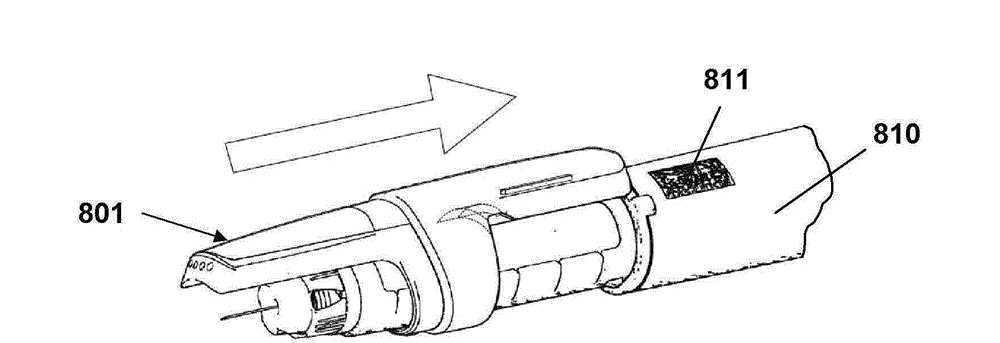
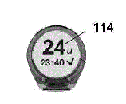
[0163] Figures 13A-13C An alternate embodiment of a two-unit measurement assembly is shown. In contrast to the embodiment of FIG. 19 , all components except the main battery 215 are located in a ring-shaped measuring unit 201 which then also includes a display 204 which in the embodiment shown is of the electronic ink type. With respect to the first embodiment, removal and reattachment of the cap can be used to define dosing events.
[0164] Figure 14A and 14B Another embodiment is shown in which all the measurement and display components described above are arranged in a single cap unit 301 , including the display 304 , all electronics 302 , and the battery 305 . In addition to the components described above, this embodiment includes an optical reader 309 adapted to capture the information provided for a given cartridge.
[0165] For all the above embodiments, communication means may be provided which allow wired or wireless data transfer, eg uploading measurement data ...
PUM
 Abstract
Description
Claims
Application Information
 - R&D
- Intellectual Property
- Life Sciences
- Materials
- Tech Scout
- Unparalleled Data Quality
- Higher Quality Content
- 60% Fewer Hallucinations
Browse by: Latest US Patents, China's latest patents, Technical Efficacy Thesaurus, Application Domain, Technology Topic, Popular Technical Reports.
© 2025 PatSnap. All rights reserved.Legal|Privacy policy|Modern Slavery Act Transparency Statement|Sitemap|About US| Contact US: help@patsnap.com