

Heat exchanger
A technology of heat exchanger and heat exchange, applied in heat exchange equipment, heat transfer modification, lighting and heating equipment, etc., can solve the problem of large area of heat exchanger, achieve high heat conduction, improve efficiency, and increase contact surface Effect
- Summary
- Abstract
- Description
- Claims
- Application Information
AI Technical Summary
Problems solved by technology
Method used
Image

Examples
Embodiment Construction
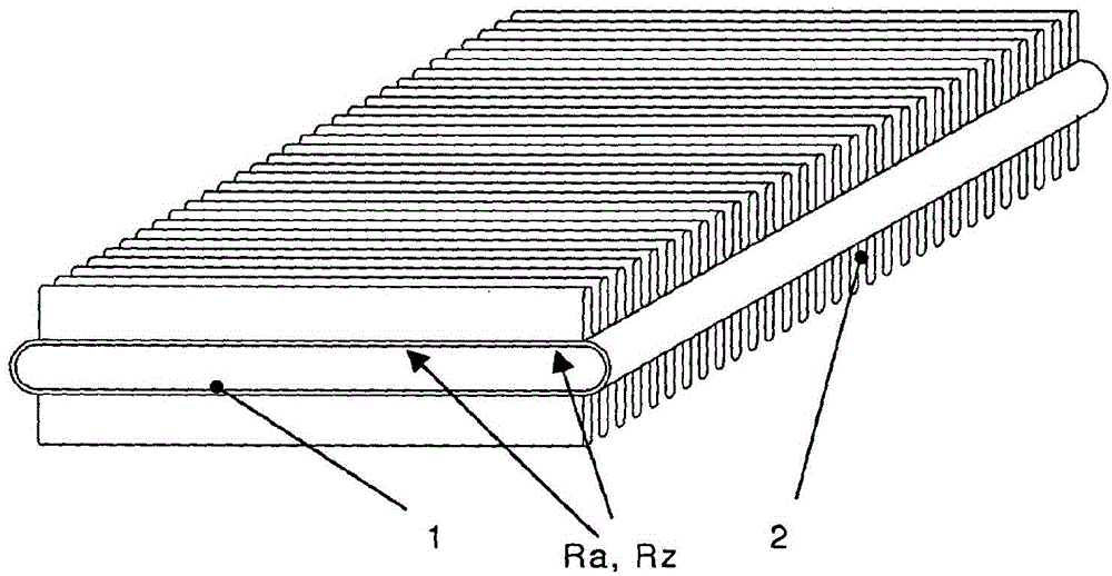
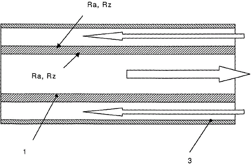
[0029] The heat exchanger of the invention comprises at least one wall separating the material or material flow. In this context, the heat exchanger according to the invention is preferably a heat exchanger for indirect heat transfer, which is characterized in that the material flow is spatially separated by a heat-conducting wall. Such heat exchangers are also referred to as heat recuperators (Rekuperator). The structural form of the heat exchanger (Regenerator) can also be considered.
[0030] According to the invention it is provided that the surface of the partition wall at least locally has an arithmetic mean roughness value Ra of 2 to 20 μm, preferably 10 μm, and / or a roughness height Rz of 10 to 50 μm, preferably 30 μm.
[0031] The commonly used abbreviation Ra represents the arithmetic mean roughness value and implements the standard DIN EN ISO4287:1998. The average roughness value is the arithmetic mean of multiple magnitudes of the roughness profile and describes ...
PUM
 Abstract
Description
Claims
Application Information