
Contactless electric power supply device

A non-contact power supply, non-contact technology, applied in the direction of electromechanical devices, circuit devices, along the track device, etc., can solve the problems of sliding power supply part wear, metal fatigue, etc., achieve low cost and avoid mutual interference effect

Active Publication Date: 2014-07-30
FUJI KK
View PDF6 Cites 2 Cited by
  • Summary
  • Abstract
  • Description
  • Claims
  • Application Information

AI Technical Summary

Problems solved by technology

However, there is concern about metal fatigue caused by reciprocating deformation on the power supply cable in the above-mentioned contact power supply mechanism, and there is also concern about wear and tear on the sliding power supply part.

Method used


Image

  • Contactless electric power supply device
  • Contactless electric power supply device
  • Contactless electric power supply device

Examples


Embodiment Construction

[0032] Before describing the embodiment, a general conventional linear motor device 9 will be described first. Figure 5 It is an explanatory drawing schematically explaining the structure of the conventional linear motor apparatus 9. The linear motor device 9 is constituted by a rail 91 , a moving body 92 , a plurality of magnets 93 , a plurality of coils 94 , a power supply cable 95 , and the like.

[0033] The rail 91 is a rail member extending along the moving direction of the moving body 92 . track 91 in Figure 5 , extending from the left front side to the right inner side along the moving direction M shown by the hollow arrow. The bottom plate 911 and the two side plates 912 and 913 are integrated to form the rail 91 . The cross-sectional shape of the rail 91 perpendicular to the moving direction is a groove shape opening upward. The moving body 92 has a substantially box shape and is mounted on the rail 91 so as to be movable. The mobile body 92 is attached to the...


PUM


Abstract

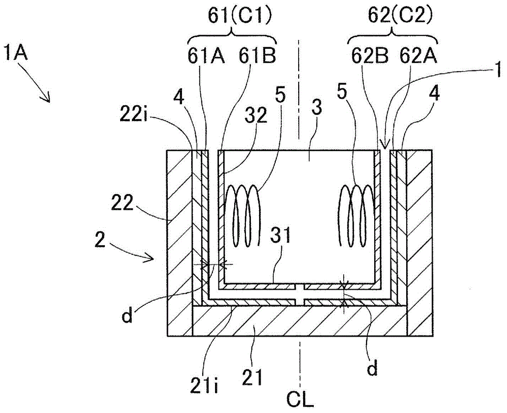
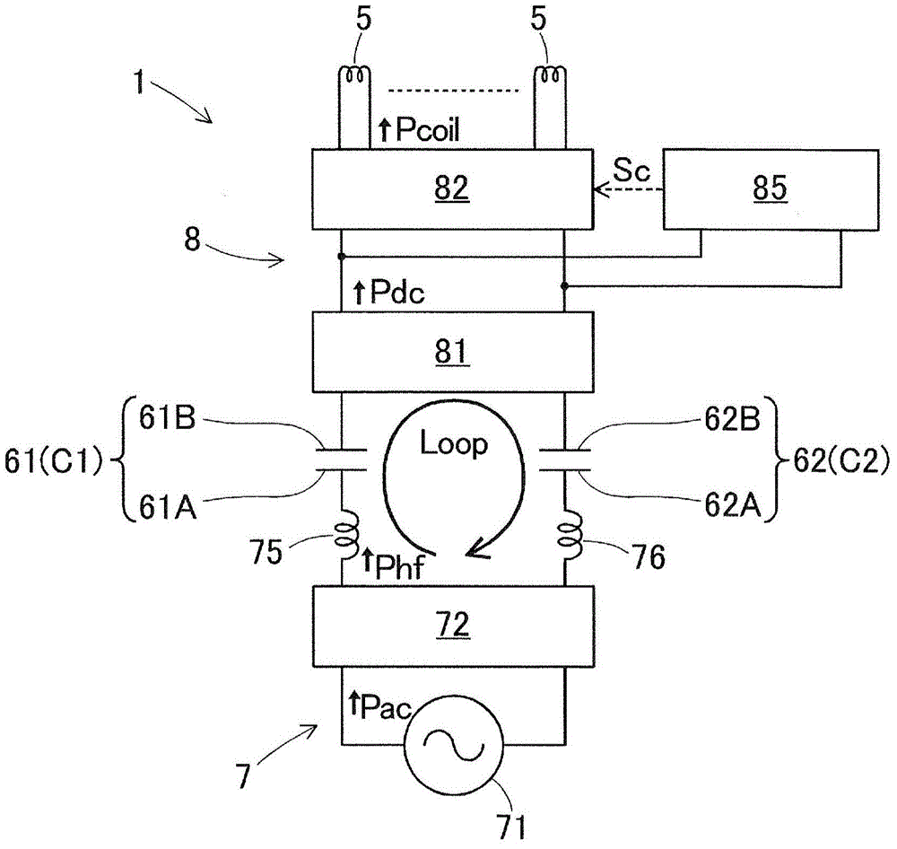
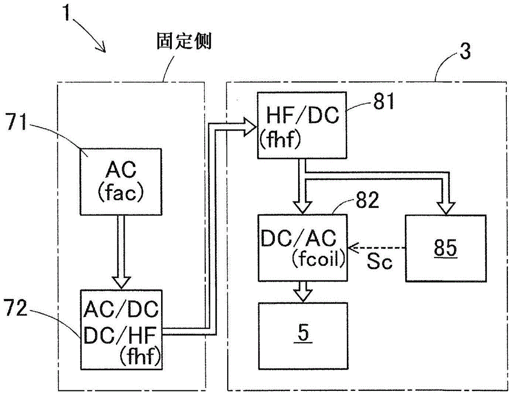
The present invention provides a contactless electric power supply device for supplying, without contact, electric power to the coils of a linear motor device provided with a track member, a movable body which is installed on the track member, magnets which are arranged in rows on the track member, and the coils which are provided to the movable body. The contactless electric power supply device is provided with: two sets of contactless electric power supply sections each having an electric power supply electrode plate which is provided to the track member so as to extend in the movement direction and an electric power receiving electrode plate which is provided to the movable body and which faces the electric power supply electrode plate, the two sets of contactless electric power supply sections being capable of supplying high-frequency electric power in a contactless manner; a high-frequency electric power source section for supplying high-frequency electric power between the electric power supply electrode plates; and an electric power conversion section which converts the high-frequency electric power supplied in a contactless manner to the electric power receiving electrode plates and which supplies the converted electric power to the coils. As a result of the configuration, the contactless electric power supply device is low cost and can perform, with large electric power supply capacity and high electric power supply efficiency, contactless electric power supply to the coils of the movable body of the linear motor device, and the contactless electric power supply does not affect the generation of a propulsion force.

Description

technical field [0001] The present invention relates to a non-contact power supply device, and more specifically, to a device for supplying power to a coil provided on a moving body of a linear motor device in a non-contact manner. Background technique [0002] There are solder printing machines, component mounting machines, reflow soldering machines, board inspection machines, etc. as board working equipment for producing boards on which many components are mounted. Many of these machines are connected by a board transfer device to form a board production line. Many of these substrate working equipment generally include a moving body that moves on the substrate to perform predetermined operations, and the moving body is driven by a linear motor device, a ball screw mechanism, or the like. Furthermore, in order to supply required electric power to the moving body, conventionally, a deformable power supply cable is used, or a sliding power supply unit capable of supplying pow...

Claims


Application Information

Patent Timeline
Patent Type & Authority Applications(China)
IPC IPC(8): H02J17/00B60M7/00H02K41/02H02K41/03
CPCB60L5/005B60M7/003H02K41/031H02K5/225H02K11/0094H02J50/12
Inventor 神藤高广野村壮志石浦直道
Owner FUJI KK
Learn More