Preparation method for microstructure particle with interference fringes
A technology of interference fringes and microstructures, which is applied in the photographic process of patterned surfaces, household appliances, optical mechanical equipment, etc., can solve problems such as limitations in the field of use, and achieve reliable anti-counterfeiting effects, high anti-counterfeiting capabilities, and precise preparation equipment Effect
- Summary
- Abstract
- Description
- Claims
- Application Information
AI Technical Summary
Problems solved by technology
Method used
Image
Examples
Embodiment 1
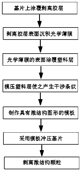
[0036] A method for preparing microstructure particles with interference fringes, the process flow is as follows figure 1 As shown, the method includes the following steps: (1) Coating a moldable and moldable release adhesive layer on the substrate, the release adhesive layer can be dissolved in an organic solvent, or can be melted by heat to facilitate peeling from the substrate; 2) Depositing an optical film on the surface of the release adhesive layer; (3) Coating a plastic layer on the surface of the optical film; (4) Molding the plastic layer to produce interference fringes; (5) Making a template with a microstructure pattern; (6) Use a template with a microstructure pattern to punch the substrate, so that the plastic layer and optical film on the substrate are pressed and broken into microstructure particles that are the same as the microstructure pattern, and the particles are pasted on the substrate through the peeling adhesive layer; (7) The microstructured particles a...
Embodiment 2
[0043] A method for preparing microstructure particles with interference fringes, the process flow is as follows figure 1 As shown, the method includes the following steps: (1) Coating a moldable and moldable release adhesive layer on the substrate, the release adhesive layer can be dissolved in an organic solvent, or can be melted by heat to facilitate peeling from the substrate; 2) Depositing an optical film on the surface of the release adhesive layer; (3) Coating a plastic layer on the surface of the optical film; (4) Molding the plastic layer to produce interference fringes; (5) Making a template with a microstructure pattern; (6) Use a template with a microstructure pattern to punch the substrate, so that the plastic layer and optical film on the substrate are pressed and broken into microstructure particles that are the same as the microstructure pattern, and the particles are pasted on the substrate through the peeling adhesive layer; (7) The microstructured particles a...
Embodiment 3
[0049] A method for preparing microstructure particles with interference fringes, the process flow is as follows figure 1 As shown, the method includes the following steps: (1) Coating a moldable and moldable release adhesive layer on the substrate, the release adhesive layer can be dissolved in an organic solvent, or can be melted by heat to facilitate peeling from the substrate; 2) Depositing an optical film on the surface of the release adhesive layer; (3) Coating a plastic layer on the surface of the optical film; (4) Molding the plastic layer to produce interference fringes; (5) Making a template with a microstructure pattern; (6) Use a template with a microstructure pattern to punch the substrate, so that the plastic layer and optical film on the substrate are pressed and broken into microstructure particles that are the same as the microstructure pattern, and the particles are pasted on the substrate through the peeling adhesive layer; (7) The microstructured particles a...
PUM
| Property | Measurement | Unit |
|---|---|---|
| thickness | aaaaa | aaaaa |
| thickness | aaaaa | aaaaa |
| particle diameter | aaaaa | aaaaa |
Abstract
Description
Claims
Application Information
 - R&D
- Intellectual Property
- Life Sciences
- Materials
- Tech Scout
- Unparalleled Data Quality
- Higher Quality Content
- 60% Fewer Hallucinations
Browse by: Latest US Patents, China's latest patents, Technical Efficacy Thesaurus, Application Domain, Technology Topic, Popular Technical Reports.
© 2025 PatSnap. All rights reserved.Legal|Privacy policy|Modern Slavery Act Transparency Statement|Sitemap|About US| Contact US: help@patsnap.com

