A kind of heat-resistant sliding block of steel rolling heating furnace

A technology of heat-resistant slide block and heating furnace, which is applied to heat treatment furnaces, furnaces, furnace types, etc., can solve the problem of increasing production and reducing consumption, reducing the time and number of shutdowns of heating furnaces, and the heat transfer of heat-resistant slide blocks and longitudinal water pipes. Defect and other problems, to achieve the effect of eliminating thermal expansion force, uniform force, reducing times and time

Active Publication Date: 2016-04-27
SHANGHAI BAOSTEEL ENERGY TECH
View PDF8 Cites 0 Cited by
  • Summary
  • Abstract
  • Description
  • Claims
  • Application Information

AI Technical Summary

Problems solved by technology

[0007] The object of the present invention is to provide a heat-resistant slide block of a steel rolling heating furnace to solve the problem of "tearing" cracks in the vertical water pipe due to the excessive thermal expansion force caused by the high temperature of the heat-resistant slide block in the existing heating furnace. Solve the problem of poor heat transfer between the heat-resistant slider and the longitudinal water pipe of the existing heating furnace, reduce the shutdown time and number of shutdowns of the heating furnace, and achieve the purpose of increasing production and reducing consumption

Method used


Image

  • A kind of heat-resistant sliding block of steel rolling heating furnace
  • A kind of heat-resistant sliding block of steel rolling heating furnace
  • A kind of heat-resistant sliding block of steel rolling heating furnace

Examples


Embodiment Construction

[0019] In order to better illustrate the present invention, a preferred embodiment is hereby combined with the attached figure 1 , figure 2 and image 3 The present invention is described in detail, specifically as follows:

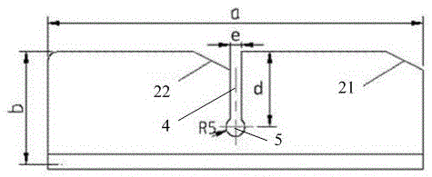
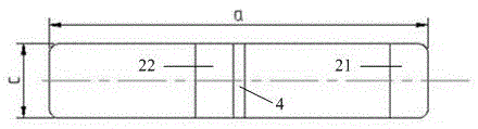
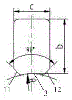
[0020] see figure 1 , figure 2 and image 3 , is a heat-resistant slider for a steel rolling heating furnace of the present invention, and the heat-resistant slider is cast from heat-resistant steel. The general size of the heat-resistant slider is: the length a of the slider is 160-200 mm, the width b of the slider is 60-70 mm, and the height c of the slider is 50-60 mm. The preferred size of the heat-resistant slider in this embodiment is: the slider The length a is 200mm, the slider width b is 70mm, and the slider height c is 50mm.

[0021] Such as figure 1 , figure 2 As shown, there is a half-groove 4 in the middle of the upper part of the heat-resistant slider, and the half-groove 4 runs through the heat-resistant slider transversely. A c...


PUM

PropertyMeasurementUnit
widthaaaaaaaaaa
depthaaaaaaaaaa
diameteraaaaaaaaaa

Abstract

The invention provides a heat-resisting sliding block of a steel rolling heating furnace. According to the heat-resisting sliding block, a semi-groove is additionally formed in an existing heat-resisting sliding block; the semi-groove transversely penetrates through the upper part of the heat-resisting sliding block; a round through hole is formed in the lower part of the heat-resisting sliding block; the lower end surface of the sliding block is an arc surface; the radius of the arc surface is identical to the outer diameter of a longitudinal water tube; an included angle of 90 degree is formed between two side surfaces of the arc surface. Due to adoption of the semi-groove, longitudinal expansion force inside the heat-resisting sliding block can be effectively eliminated, longitudinal water tube breakage caused by the longitudinal expansion force of the heat-resisting sliding block is avoided, the arc surface at the lower end surface can be seamlessly adhered to the longitudinal water tube, and an angle weld joint for welding is formed by the included angle of 90 degrees between the two side surfaces, so that the heat conduction of the longitudinal water tube of the heat-resisting sliding block is enhanced, the temperature of the heat-resisting sliding block is effectively reduced, the longitudinal expansion force generated inside the heat-resisting sliding block is further reduced, and the transverse breakage of the longitudinal water tube is avoided. The heat-resisting sliding block of the steel rolling heating furnace, which is provided by the invention, is simple in production process and low in cost, the frequency and the time for stopping the furnace for overhaul are effectively reduced and shortened, and thus the purposes of yield increase, energy conservation and consumption reduction are achieved.

Description

technical field [0001] The invention relates to the technical field of the water beam slider structure of a steel rolling heating furnace, in particular to a heat-resistant slider of a steel rolling heating furnace. Background technique [0002] The heating furnace is an important equipment in the rolling mill. Its function is to heat the steel ingot or billet to the rolling temperature. On the water pipe), the steel ingot or billet is pushed from the rear of the heating furnace to the head of the heating furnace by the pusher to complete the heating. [0003] The heat-resistant slider of the existing heating furnace generally has a size of 200×70×50 mm, is made of heat-resistant steel, and the heat-resistant slider is welded on the longitudinal water beam. [0004] During the production process, the welding part of the vertical water beam and the heat-resistant slider will be fractured transversely, which will cause the water in the vertical water beam to leak out and the ...

Claims


Application Information

Patent Timeline
Patent Type & Authority Patents(China)
IPC IPC(8): C21D9/70
Inventor 黄恩民
Owner SHANGHAI BAOSTEEL ENERGY TECH
Why Eureka
Try Eureka