Stilling pool with laterally-effluent revolution and rolling energy dissipation function

A stilling pool and trough pool technology, applied in water conservancy projects, marine engineering, coastline protection and other directions, can solve the problems of large amount of excavation works and unsatisfactory energy dissipation effect, so as to reduce construction costs and reduce excavation works. The effect of reducing the amount of construction and reducing the difficulty of construction

Inactive Publication Date: 2014-08-06
SICHUAN UNIV
View PDF5 Cites 10 Cited by
  • Summary
  • Abstract
  • Description
  • Claims
  • Application Information

AI Technical Summary

Problems solved by technology

[0006] Aiming at the technical status and deficiencies of traditional stilling pools, the purpose of the present invention is to provide a stilling pool with lateral outflow swirl and rolling energy dissipation that overturns the planar layout structure of traditional

Method used


Image

  • Stilling pool with laterally-effluent revolution and rolling energy dissipation function
  • Stilling pool with laterally-effluent revolution and rolling energy dissipation function
  • Stilling pool with laterally-effluent revolution and rolling energy dissipation function

Examples


Embodiment 1

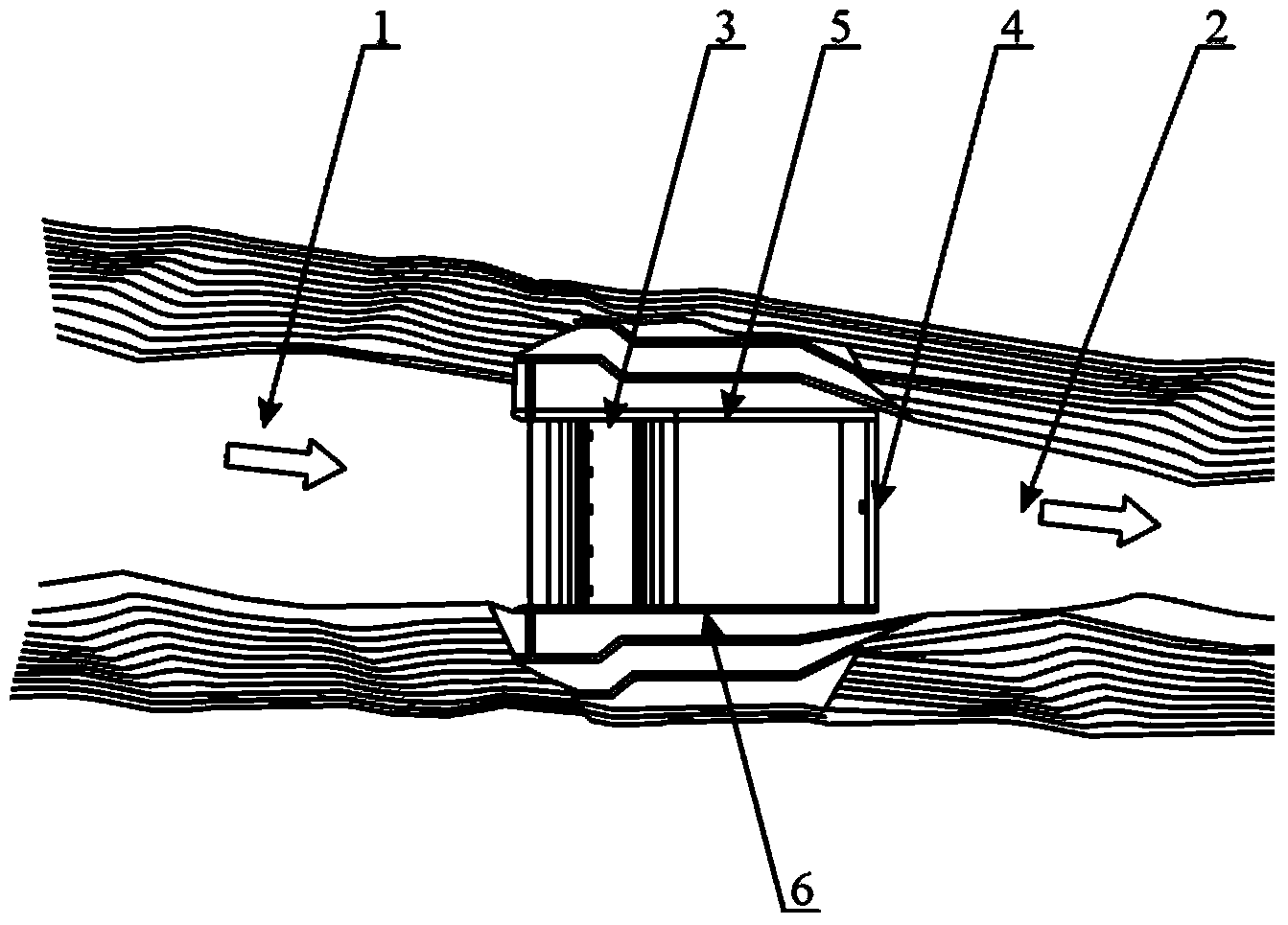
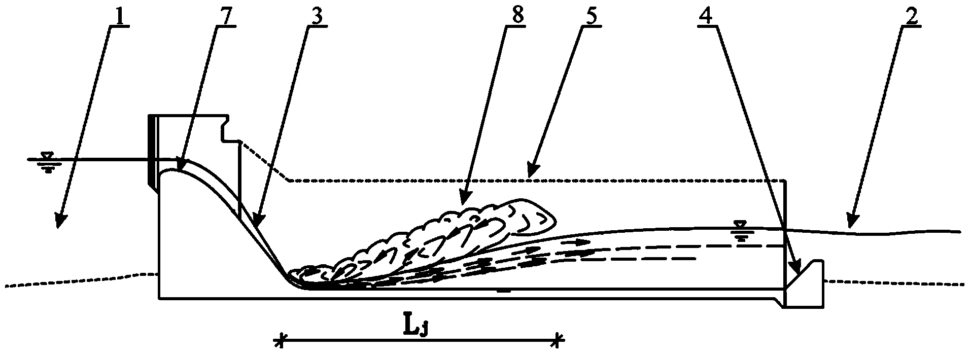
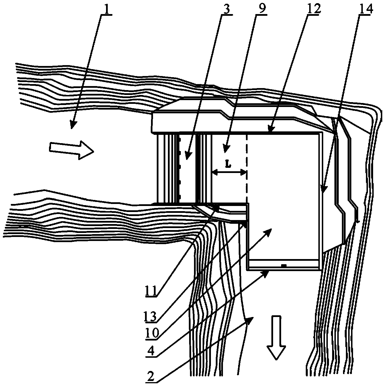
[0031] The stilling basin for the energy dissipation of the lateral outflow swirling rolling given in this embodiment, such as Figure 3A As shown, it is composed of a part of the tank 9 behind the overflow dam arranged in the upstream channel and a part of the tank 10 connected to the part of the tank and located in front of the water flow inlet of the downstream channel. The axes of the two parts of the tank intersect at 90°. The water flowing through the overflow dam 3 enters the stilling basin to generate a hydraulic jump 8, and then flows out of the stilling basin in a sideways rolling manner, so that the water flow can dissipate energy. A tail sill 4 is arranged at the tail of the tank pool 10 in front of the water inlet of the downstream channel. The inner side wall 11 and the outer side wall 12 of the part of the trough behind the overflow dam of the stilling pool, and the inner side wall 13 and the outer side wall 14 of the part of the trough in front of the water inl...

Embodiment 2

[0036] The structure of the stilling pool for the energy dissipation of the lateral outflow swirling roll given in this embodiment is as follows: Figure 3B As shown, it is basically the same as the stilling basin for lateral flow and rolling energy dissipation described in Embodiment 1, the difference is that the length of the inner side wall 11 of the part of the tank behind the overflow dam is the hydraulic jump of the stilling basin. 1.2 times the length, the tail of the trough in front of the water inlet of the downstream river is not provided with the tail sill 4, and the inner side wall 11, the outer side wall 12 of the trough behind the overflow dam of the stilling pool and the water flow inlet of the downstream river are not provided. The height of the inner side wall 13 and the outer side wall 14 of the part of the tank in the front is equal to 1.2 times of the design flood level height.

Embodiment 3

[0038] The structure of the stilling pool for the energy dissipation of the lateral outflow swirling roll given in this embodiment is as follows: Figure 3B As shown, it is basically the same as the stilling basin of the lateral flow and rolling energy dissipation described in Embodiment 1, the difference is that the length of the inner side wall 11 of the part of the tank behind the overflow dam is the hydraulic jump of the stilling basin. 1.2 times the length, the tail of the trough in front of the water inlet of the downstream river is not provided with the tail sill 4, and the inner side wall 11, the outer side wall 12 of the trough behind the overflow dam of the stilling pool and the water flow inlet of the downstream river are not provided. The inner side wall 13 and the outer side wall 14 of the front part of the trough are slope structure side walls inclined to the outside, and their height is equal to 1.1 times of the design flood level.

[0039] The schematic diagram...


PUM


Abstract

The invention discloses a stilling pool with the laterally-effluent revolution and rolling energy dissipation function. The stilling pool is composed of a first partial tank and a second partial tank, wherein the first partial tank is located at the back of an overflow dam arranged in an upstream river channel, and the second partial tank is connected with the first partial tank and located in front of a current inlet of a downstream river channel. The axes of the two partial tanks intersect. The overall stilling pool is of a bent structure in the plane direction. Current flowing through the overflow dame enters the stilling pool, generates hydraulic jump and then flows out of the stilling pool in a lateral revolution and rolling mode, so that energy dissipation of the current is realized. The stilling pool with the laterally-effluent revolution and rolling energy dissipation function overturns the traditional stilling pool plane layout structure, fills the gap in the prior art that a stilling pool suitable for being built at a river channel bent channel is not available, and solves the problems that a traditional stilling pool is large in excavation work amount. unsatisfactory in energy dissipation effect and the like.

Description

technical field [0001] The invention belongs to the technical field of flood discharge and energy dissipation of water conservancy and hydropower projects, and in particular relates to a stilling pool suitable for the overall energy dissipation of a hub arranged at a bend of a river. Background technique [0002] The stilling basin is an energy dissipation facility that promotes the generation of an underflow hydraulic jump downstream of a river or downstream of a discharge structure. The stilling pool can quickly change the rapid flow of the discharge into a slow flow. Generally, it can eliminate 40% to 70% of the kinetic energy of the discharge flow, and can shorten the length of the apron. It is an effective and economical energy dissipation facility. In the design of stilling basins in water conservancy projects, the length is a very important factor affecting the energy dissipation effect of stilling basins, and the length of stilling basins is closely related to the le...

Claims


Application Information

Patent Timeline
IPC IPC(8): E02B8/06
Inventor 邓军许唯临刘善均曲景学王韦张建民田忠张法星卫望汝
Owner SICHUAN UNIV
Why Eureka
Try Eureka