

Dual-valve orifice-area-variable fuel nozzle
A fuel nozzle and nozzle hole area technology, which is used in fuel injection devices, engine components, machines/engines, etc., can solve the problem that fuel nozzles cannot achieve flexible and adjustable fuel injection rules, and achieve the effect of improving fuel atomization.
- Summary
- Abstract
- Description
- Claims
- Application Information
AI Technical Summary
Problems solved by technology
Method used
Image

Examples
Embodiment Construction
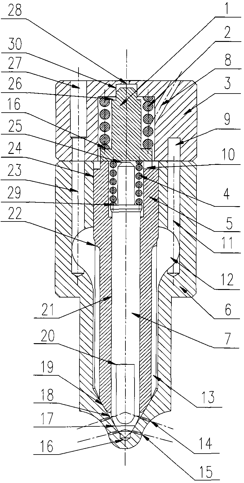
[0021] Preferably, the oil inlet ring groove 9 of the adapter seat 3 communicates with the oil inlet hole 27 of the adapter seat. The nozzle body 6 includes two oil inlet passages, the main oil inlet hole 23 and the auxiliary oil inlet hole 11. The main oil inlet hole 23 and the auxiliary oil inlet hole The oil holes 11 communicate with the oil tanks 12 respectively.
[0022] Preferably, the number of milling planes 20 is 2 to 4, and they are evenly arranged in the circumferential direction.
[0023] Preferably, the number of oil inlet grooves 13 is 2 to 4, and they are evenly arranged in the circumferential direction.
[0024] Preferably, the hydraulic diameter of the auxiliary nozzle hole 14 is smaller than 1 / 4 of the hydraulic diameter of the main nozzle hole 15 .
[0025] Preferably, the cone angle of the conical surface where the main injection hole 15 and the auxiliary injection hole 14 are located is in the range of 140°-160°, and the number of injection holes is in th...
PUM
 Abstract
Description
Claims
Application Information