A high-efficiency power generation device worn on the foot

A power generation device and foot technology, applied in the field of machinery and electronics, can solve problems such as time-consuming and labor-intensive, defects, moisture-proof and waterproof, and small electric power

Active Publication Date: 2019-08-02
钟声
View PDF5 Cites 0 Cited by
  • Summary
  • Abstract
  • Description
  • Claims
  • Application Information

AI Technical Summary

Problems solved by technology

This leads to some of our common manual or pedal, or power generation equipment designed as shoes, which are either huge and bulky and inconvenient to carry, or are extra time-consuming and labor-intensive, especially those designed as an integrated shoe. Although these products are easy to carry, they are inconvenient for maintenance due to their structural defects, such as moisture-proof and waterproof, and it is not easy to complete the power collection and many other problems. There are also many problems such as requiring too fast movement frequency during work, which can easily make people tired, and when people do work, they have to use force. The force is not directly proportional to the electric energy generated
What is especially unbearable is that the output power is too small, and it can only light up a few small LED lights. This kind of practical value is simply not worth mentioning, and it can only be a gimmick

Method used


Image

  • A high-efficiency power generation device worn on the foot
  • A high-efficiency power generation device worn on the foot
  • A high-efficiency power generation device worn on the foot

Examples


Embodiment Construction

[0029] specific implementation plan

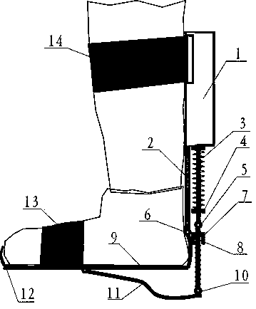
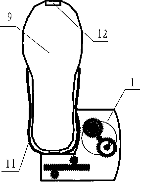
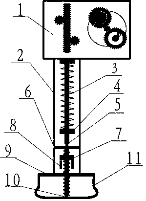
[0030] Below to figure 1 Taking the planar structure of the overall rendering of the right foot as an example, the specific operation mode of the simulation is as follows:

[0031] When the right foot is stepping down, the concave arc surface in the middle section of the frame-type overturn bracket 11 first touches the ground and the supporting rod 5 moves upward, and the shoe presses the shoe supporting plate 9 to move downward, driving the main support back plate 2 and fixing The generator component 1 on the main support backplane moves downward, the tension spring 3 sandwiched between the generator 1 and the stopper 4 is compressed, and the connecting rod 5 continues upward relative to the generator 1, pushing the generator 1 Power generation; when the right foot is doing the leg-lifting action, the frame-type flip bracket 11 touches the ground and leaves the ground at one end, the upward force of the jacking connecting rod 5 disappear...


PUM


Abstract

The invention provides an external electricity generation mechanism which can be worn at a foot and is fastened to the outside of a shoe and the position of a shank through a tying band and the like, and discloses an efficient generating set worn at the foot. According to the basic principle of the efficient generating set worn at the foot, a transmission mechanism is triggered to be actuated along with the movement of the foot of a human body, the movement enables a spring in the transmission mechanism to be pressed due to stress or be unfolded due to force release and to drive a connecting rod to move upwards and downwards in a reciprocating mode, and the generating set is driven to generate electricity. Different from other products, the overall structure of the efficient generating set is separated from clothes and independently arranged as a whole, serves as an additional device and acts by virtue of the gravity of the human body along with human motions. Due to the ingenious mechanism, the efficient generating set worn at the foot has the functions of stroke adjustment and press adjustment to adapt to the movement status of individuals with different weights at different speeds. As a follow-up additional device, the efficient generating set worn at the foot has the advantages that the human body does not need to spend extra movement energy or extra time in the movement process, and by the adoption of high-power generating set components, kinetic energy of the human body can be efficiently collected and efficiently converted into electricity at the same time.

Description

technical field [0001] The invention relates to the technical fields of machinery and electronics, in particular to a power generating device worn on the foot and capable of generating electric energy with the movement of the human body. Background technique [0002] With the development of modern technology, people are becoming more and more accustomed to carrying a large number of electronic products that consume electric energy with them, and regard them as indispensable tools in work and life, which puts forward many special requirements for timely and convenient electric energy supply . Especially in tourism, hiking, field marching, etc., it may cause extremely serious consequences because of the inability to guarantee electric energy. Due to the demand for electric energy all the time and everywhere, some portable small power generation equipment with the help of human body actions have also emerged as the times require. We know that human body movements are realized...

Claims


Application Information

Patent Timeline
IPC IPC(8): F03G1/00F03G5/00
Inventor 钟声
Owner 钟声
Why Eureka
Try Eureka