Coating structure for low-temperature heat insulation container and coating method of coating structure

A technology of low-temperature heat insulation and cladding structure, which is applied in the direction of pressure vessels, fixed-capacity gas storage tanks, mechanical equipment, etc. It can solve the problems of reducing vacuum efficiency, affecting vacuum performance, and easily generating debris, so as to reduce vacuum pumping And the effect of subsequent vacuum maintenance, shortened heat insulation coating time, and simplified process engineering

Active Publication Date: 2014-08-06
湖北三江航天江北机械工程有限公司
View PDF6 Cites 14 Cited by
  • Summary
  • Abstract
  • Description
  • Claims
  • Application Information

AI Technical Summary

Problems solved by technology

In the production and processing of low-temperature heat-insulating containers, it is necessary to wrap the heat-insulating material on the container liner layer by layer through aluminum foil tape. The specific method is to slowly rotate the container liner on the wrapping machine, wrap the heat-insulating paper on the liner And in the winding process, skilled workers are required to press it firmly. Since the insulation paper is relatively brittle, the inner tank should not rotate too fast, otherwise it is easy to break the insulation paper, which limits the entire winding process. The speed reduces the coating efficiency of the heat insulation material, and it is difficult to handle the head and pipeline parts, which is prone to debris. Specifically, when the aluminum foil wraps the spherical surface (the head), it is easy to produce wrinkles, It is easier to break after being beaten. In addition, the heat insulation paper itself is relatively brittle. At the pipeline, the heat insulation material must be cut to avoid the pipeline. The debris will be hidden between the composite layers at the beginning, the vacuum chamber is easy to be drawn out, and it is very likely to be blocked in the vacuum port, which reduces the vacuum efficiency and affects the vacuum performance, and the artificial influence on product quality is too large

Method used


Image

  • Coating structure for low-temperature heat insulation container and coating method of coating structure
  • Coating structure for low-temperature heat insulation container and coating method of coating structure
  • Coating structure for low-temperature heat insulation container and coating method of coating structure

Examples


Embodiment Construction

[0043]Below in conjunction with accompanying drawing and specific embodiment the present invention is described in further detail:

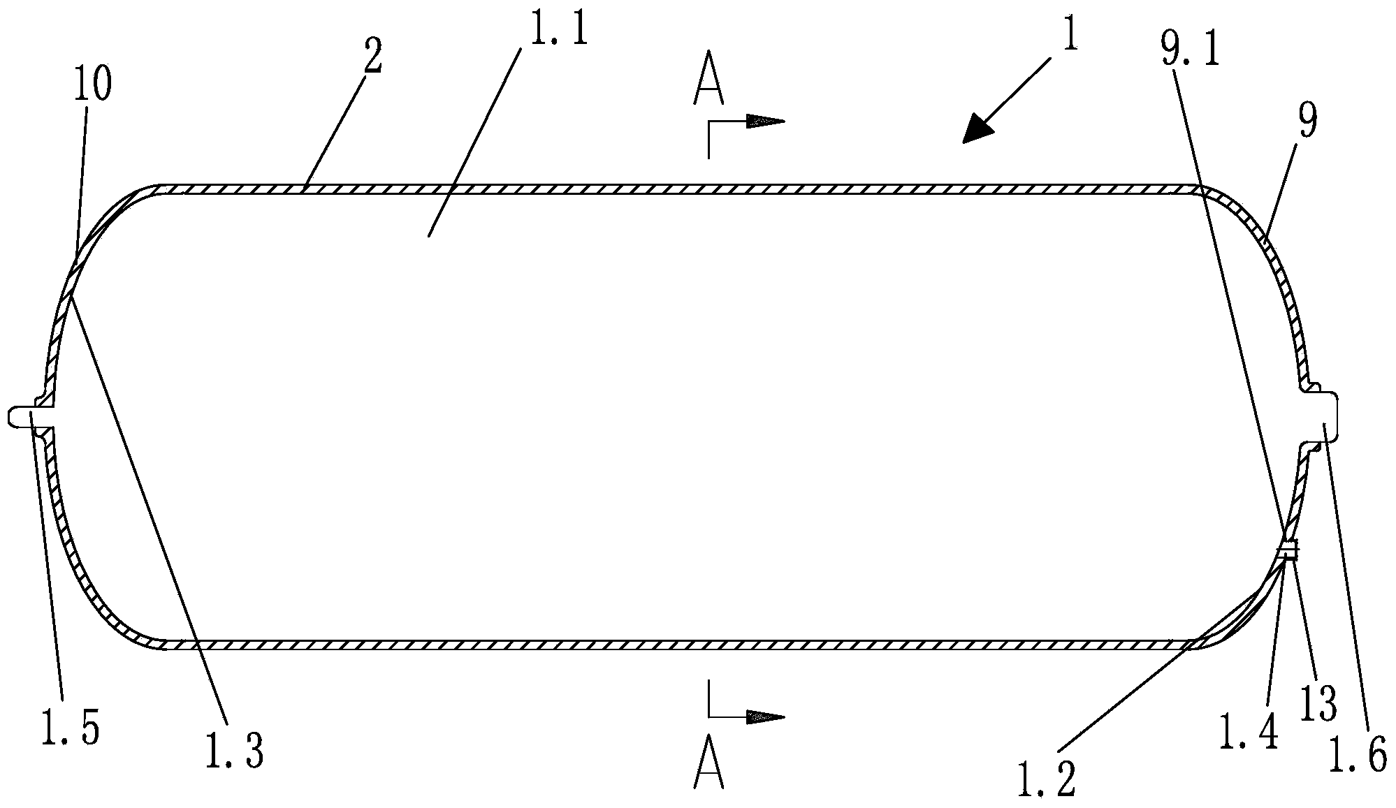
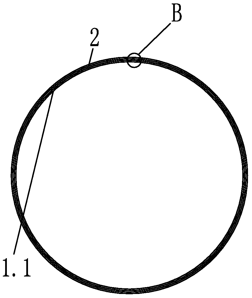
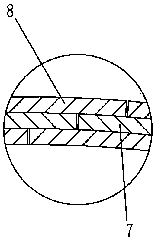
[0044] Such as Figure 1-12 The cladding structure of the low-temperature heat-insulating container shown includes an inner tank 1, the inner tank 1 has a cylindrical tank body 1.1, a spherical front head 1.2 connected to the front end of the cylindrical tank body 1.1 and connected to the rear of the cylindrical tank body 1.1 The spherical rear head 1.3 at the end, the center of the spherical front head 1.2 is provided with a front support rod 1.6, the surface of the spherical front head 1.2 is provided with a pipe joint 1.4, and the center of the spherical rear head 1.3 is provided with a rear support rod 1.5 , it also includes a thermal insulation quilt 2, a front sealing cap 3 and a rear sealing cap 4, one side of the thermal insulation quilt 2 is provided with a positive step lap edge 7, and the other side of the thermal insulation quilt 2 is...


PUM


Abstract

The invention discloses a coating structure for a low-temperature heat insulation container. Stair-step trapezoid overlapped edges are arranged on one side of a heat insulation quilt of the coating structure, and anti-stair-step trapezoid overlapped edges are arranged on the other side of the heat insulation quilt; front trapezoid heat insulation blocks are arranged at the front end of the heat insulation quilt; a first pipe interface yield hole is formed in one trapezoid heat insulation block which corresponds to a pipe interface; back trapezoid heat insulation blocks are arranged at the back end of the heat insulation quilt; the surface of a cylindrical container is coated with the heat insulation quilt, and the forward trapezoid overlapped edges and the backward trapezoid overlapped edges are bonded; the external surface of a spherical surface front head around a front supporting rod is coated with the front trapezoid heat insulation blocks, thereby forming a front end spherical surface coating layer; the first pipe interface yield hole is sleeved with the pipe interface; the external surface of a spherical surface back head around a back supporting rod is coated with the back trapezoid heat insulation blocks, thereby forming a back end spherical surface coating layer; the external surface of the front end spherical surface coating layer is coated with a front sealing cap, and the external surface of the back end spherical surface coating layer is coated with a back sealing cap. According to the coating structure, the winding and coating efficiency of a thermal insulating material is improved, and the effect of maintaining vacuum is improved.

Description

technical field [0001] The invention relates to the technical field of low-temperature containers, in particular to a cladding structure and a cladding method for a low-temperature heat-insulating container. Background technique [0002] Cryogenic insulation containers have been widely used in industrial production and transportation due to their safety and high efficiency. Most low-temperature heat-insulating containers have a double-layer structure including an inner tank and an outer shell. In order to reduce radiation heat transfer, the inner tank needs to be covered with an insulating layer. At present, the heat insulation layer is mostly made of winding heat insulation material outside the inner tank, and the heat insulation material is alternately compounded by aluminum foil with high reflectivity and low temperature heat insulation paper with low thermal conductivity. In the production and processing of low-temperature heat-insulating containers, it is necessary to ...

Claims


Application Information

Patent Timeline
Patent Type & Authority Applications(China)
IPC IPC(8): F17C1/12
Inventor 吴凡坤唐英国郑永刚余峰康斌胡健
Owner 湖北三江航天江北机械工程有限公司
Why Eureka
Try Eureka