
Orientation identification method of ultrasonic array crack defects based on vector full-focusing imaging

A direction recognition, ultrasonic array technology, applied in the direction of using sonic/ultrasonic/infrasonic waves to analyze solids and process the response signals of detection, which can solve problems such as inability to recognize

Inactive Publication Date: 2014-08-06
BEIJING UNIV OF TECH
View PDF6 Cites 24 Cited by
  • Summary
  • Abstract
  • Description
  • Claims
  • Application Information

AI Technical Summary

Problems solved by technology

However, the all-focus imaging method cannot identify the direction of crack defects

Method used


Image

  • Orientation identification method of ultrasonic array crack defects based on vector full-focusing imaging
  • Orientation identification method of ultrasonic array crack defects based on vector full-focusing imaging
  • Orientation identification method of ultrasonic array crack defects based on vector full-focusing imaging

Examples


Embodiment Construction

[0050] The present invention will be described in further detail below in conjunction with the accompanying drawings and embodiments.

[0051] The detection instrument in this example is Multi2000 series phased array equipment, which includes ultrasonic excitation / reception module, acquisition module and phased array linear array transducer. The center frequency of the linear array transducer used in the experiment is f=5MHz, the total number of array elements is N=32, the width of a single array element is a=0.5mm, and the distance between the centers of two adjacent array elements is p=0.6mm. The propagating wave velocity in the component is c=5900m / s, then the wavelength The detection object is a round steel forging with a diameter of 300mm and a thickness of 40mm.

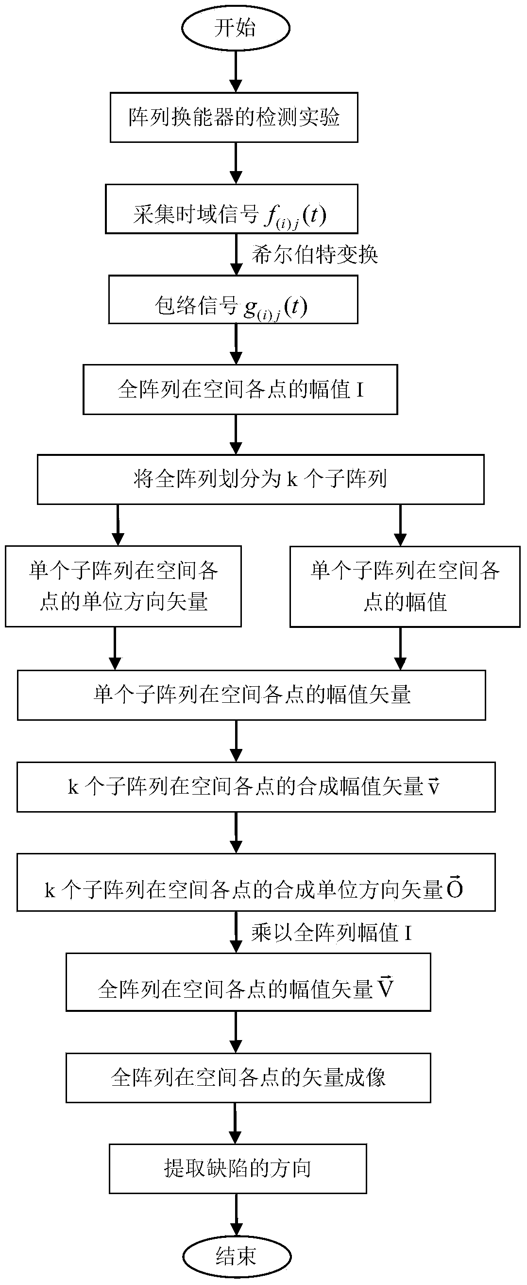
[0052] The specific steps of an ultrasonic array crack defect direction identification method based on vector total focus imaging proposed by the present invention are as follows:

[0053] Step 1: In such as...


PUM


Abstract

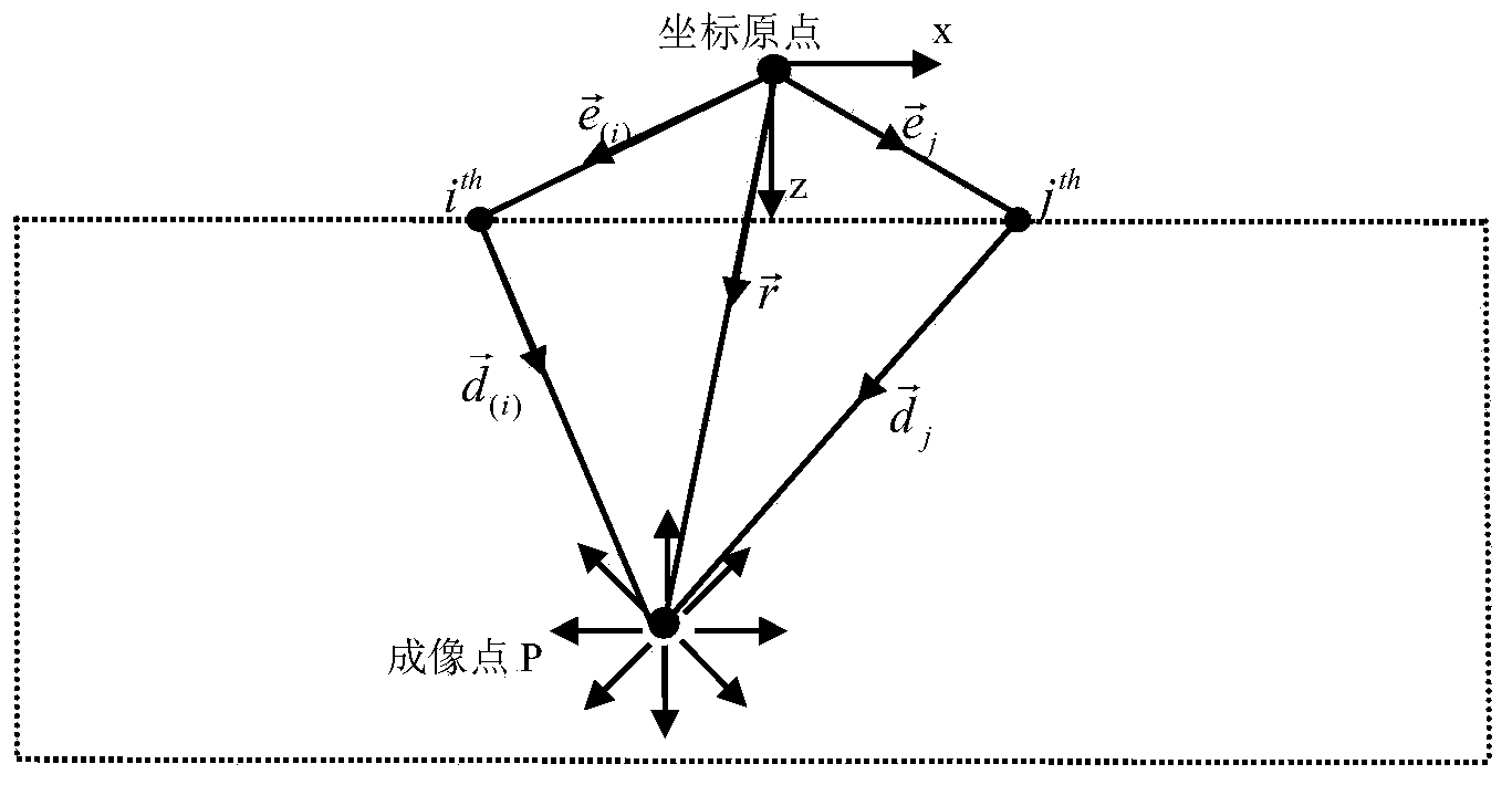
The invention relates to an orientation identification method of ultrasonic array crack defects based on vector full-focusing imaging, and belongs to the field of nondestructive testing. According to the method, vector full-focusing treatment is performed on signals received by a transducer array so as to obtain a global vector diagram, the positions of the defects are determined by the strongest energy of reflected signals at the defects, then local vector diagrams of the defects are extracted according to the positions of the defects, and finally the directions of the vectors are determined by utilizing the directions of vectors in the local vector diagrams. According to the principle of vector full-focusing imaging, a plurality of sub-arrays are constructed in the transducer array, the unit direction vector at any imaging point is calculated through the sub-arrays, and echo amplitude after compensation at any imaging point to the transducer array is vectorized by utilizing the unit direction vector, so that amplitude vector at any imaging point is obtained.

Description

technical field [0001] The invention relates to an ultrasonic array crack defect direction recognition method based on vector total focus imaging. The method relates to the direction recognition technology of crack defects and belongs to the technical field of non-destructive testing. Background technique [0002] As the basic components of various mechanical equipment, forgings are widely used in key fields such as aerospace, nuclear power, and ships. Due to the complex shape and production process of forgings, crack defects are prone to occur during the production process. Defects in forgings will significantly reduce their mechanical properties, and even break during use, resulting in serious safety and quality accidents. There is a certain directionality for crack defects, and obtaining the directionality of defects can effectively improve the forging production process and increase production efficiency. [0003] Ultrasonic flaw detection, as one of the five conventio...

Claims


Application Information

Patent Timeline
Patent Type & Authority Applications(China)
IPC IPC(8): G01N29/06G01N29/44
Inventor 焦敬品孙欣蓉杜礼吴斌何存富
Owner BEIJING UNIV OF TECH
Learn More