A multi-beam emission three-dimensional imaging method

A three-dimensional imaging, multi-beam technology, applied in the re-radiation of sound waves, the reflection/re-radiation of radio waves, and the use of re-radiation, etc., can solve the problem of poor robustness, large computational burden of matched filtering processing, and orthogonal coding of signal waveforms Complex problems, to achieve the effect of saving array elements and reducing requirements

Inactive Publication Date: 2016-04-13
NORTHWESTERN POLYTECHNICAL UNIV
View PDF2 Cites 0 Cited by
  • Summary
  • Abstract
  • Description
  • Claims
  • Application Information

AI Technical Summary

Problems solved by technology

In order to suppress cross-correlation interference and auto-correlation sidelobe interference, these coded signals need to use a large number of subcodes to synthesize long pulse signals, which brings a large computational burden to the matched filter processing at the receiving end.
In addition, the waveforms of these quadrature-coded signals are too complex, and their robustness in harsh environments is not as good as traditional simple waveforms, such as continuous wave (CW: Continuous Wave) pulses and linear frequency modulation (LFM: Linear Frequency Modulation) pulses

Method used


Image

  • A multi-beam emission three-dimensional imaging method
  • A multi-beam emission three-dimensional imaging method
  • A multi-beam emission three-dimensional imaging method

Examples


Embodiment Construction

[0024] The present invention will be further described below in conjunction with the accompanying drawings and embodiments, and the present invention includes but not limited to the following embodiments.

[0025] Main content of the present invention has:

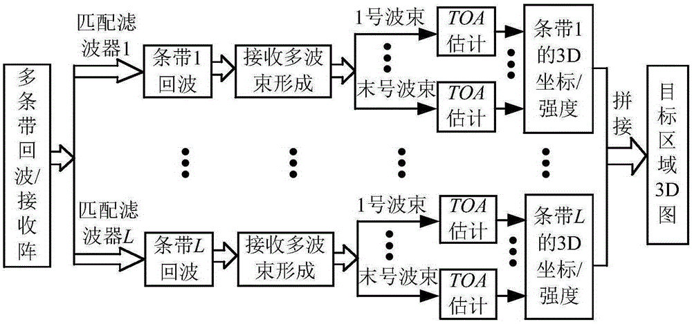
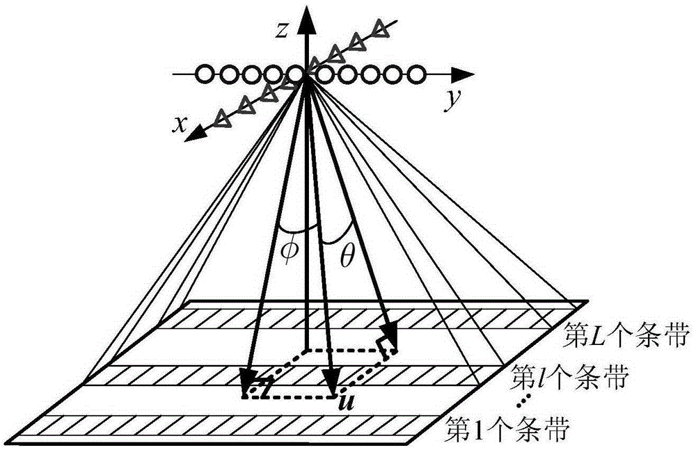
[0026] 1. Multiple independent sub-pulses are weighted before emission to ensure that a sub-pulse can irradiate a specific strip. These emission-weighted sub-pulses are superimposed into a single pulse in the time domain. Two mutually perpendicular linear arrays are used as the transmitting array and the receiving array respectively. The transmitting linear array emits superimposed independent pulses, and simultaneously forms multiple transmitting beams within a ping. These transmitting beams are all generated by their corresponding sub-pulses and point to different strips according to the transmitting weight. The receiving linear array collects the echoes, and uses matched filtering to separate the echoes generated by d...


PUM


Abstract

The invention provides a multi-beam transmission three-dimensional imaging method. A transmitting array and a receiving array are uniform linear arrays intersecting with each other perpendicularly. A transmitted signal is formed by overlaying a plurality of independent sub-pulses on the time domain, and transmission weighting is carried out on each sub-pulse before transmission, so that the sub-pulses point to corresponding strips respectively. Each transmission array element of the transmitting array transmits the same sub-pulses at the same moment. The receiving array collects echoes of each strip. A copy of each sub-pulse is used for carrying out matched filtering on the echoes on the receiving array, beam forming is carried out after the echo components corresponding to each sub-pulse are separated, and then a three-dimensional image of each strip can be obtained. The three-dimensional images of all the strips are spliced to obtain the three-dimensional image of a whole target area. According to the multi-beam transmission three-dimensional imaging method, the work efficiency is much higher than that of a traditional crossed-shaped array imaging system, and use of complicated quadrature coding signals is avoided.

Description

technical field [0001] The invention relates to an array imaging method. Background technique [0002] A three-dimensional imaging system usually uses an array such as a rectangular planar array to collect and process echoes (Murino V and Trucco A, Three-dimensional image generation and processing in underwater acoustic vision, in Proc. IEEE, 2000; 88(12): 1903-1948.). However, the use of a planar array will bring about the disadvantage of a large number of array elements, resulting in an extremely high cost of the 3D imaging system. In order to save the cost of array elements, a cross array composed of two mutually perpendicular linear arrays can be used for three-dimensional imaging (de Jong CD, Lachapelle G, Skone S. Multibeam sonartheory of operation. Delft: Delft University Press, 2002.). The cross array can obtain three-dimensional imaging capabilities similar to the rectangular planar array through its own movement, and can also perform three-dimensional imaging thro...

Claims


Application Information

Patent Timeline
Patent Type & Authority Patents(China)
IPC IPC(8): G01S13/89
CPCG01S15/34
Inventor 孙超刘雄厚
Owner NORTHWESTERN POLYTECHNICAL UNIV
Why Eureka
Try Eureka