Optical channel monitor based on DLP

A monitor and optical channel technology, which is applied in the field of optical communication devices, can solve the problems of slow scanning detection speed, incompatibility, high price, etc., and achieve the effect of fast scanning detection speed and adjustable bandwidth.

Inactive Publication Date: 2014-08-06
SHANGHAI BRANCH FUZHOU GAOYI COMM CO LTD
View PDF3 Cites 2 Cited by
  • Summary
  • Abstract
  • Description
  • Claims
  • Application Information

AI Technical Summary

Problems solved by technology

An optical channel monitor consisting of a tunable filter and a single-spot detector, where there are mechanically rotatable components (such as filtering by rotating a diaphragm) or thermally tuned components (such as an etalon that is filtering by thermal tuning) , the scanning detection speed has the disadvantage of being too slow
The optical channel monitor composed of a grating and an array detector is expensive due to the use of an array photodetector.
In addition, the two implementation methods have a common shortcoming, which cannot be used in different wavelength interval networks. When the network is upgraded, the optical channel monitor needs to be replaced

Method used


Image

  • Optical channel monitor based on DLP
  • Optical channel monitor based on DLP
  • Optical channel monitor based on DLP

Examples


Embodiment Construction

[0022] The present invention will be further described below in conjunction with the accompanying drawings and specific embodiments.

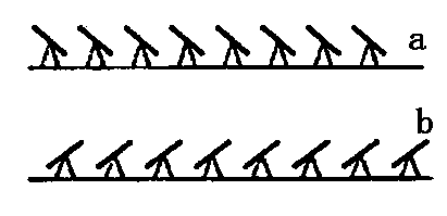
[0023] The core of the DLP (Digital Light Procession) digital light processor used in the present invention is a digital micromirror device DMD (Digital Micromirror Device) developed by TI (Texas Instruments). DMD is an array of extremely small mirrors (a few microns to a dozen microns). These micro mirrors are suspended and can be tilted to both sides by about 10~12 degrees, so as to form reflections in two directions, such as figure 1 and 2 As shown, the state of each micromirror can be independently controlled by DLP (Digital Light Processor).

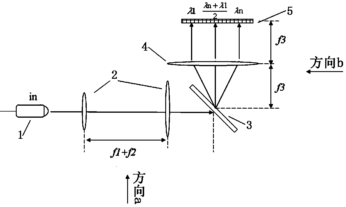
[0024] The present invention adopts the combination of grating and DLP to realize the optical channel monitor with adjustable bandwidth and adjustable channel spacing, including collimator, beam shaping unit, grating, lens group, DLP and photoelectric detector; the incident light is collimated by th...


PUM


Abstract

The invention relates to the field of optical communication devices, and discloses an optical channel monitor based on a DLP. The optical channel monitor based on the DLP comprises a collimator, a light beam shaping unit, an optical grating, a lens set, the DLP and a photoelectric detector, wherein incident light is collimated by the collimator, then emitted to the light beam shaping system and diffracted by the optical grating, the diffracted light beam is collimated by the lens set, emitted to the DLP and then diffracted by the DLP, and part of the light beam passes through the lens set, the optical grating and the light beam shaping unit again and then is emitted to the photoelectric detector. According to the optical channel monitor based on the DLP, the optical grating is combined with the DLP, optical channel monitoring with an adjustable band width and an adjustable channel interval is achieved, the scanning and detection speed is high, the optical channel monitor based on the DLP is suitable for a network without a wavelength interval, and the optical channel monitor does not need to be replaced in the network upgrading process.

Description

technical field [0001] The invention relates to the field of optical communication devices, in particular to a DLP-based optical channel monitor. Background technique [0002] In the optical fiber transmission system, as the communication capacity increases, it is necessary to use WDM technology to transmit multiple wavelengths of composite light with the same optical fiber, and the wavelength interval is getting smaller and smaller, 200G, 100G, 50G, 25G , and transmissions with different wavelength intervals exist simultaneously. With the use of multiple optical wavelengths and more and more optical nodes, optical channel monitoring becomes more and more important, and optical signal transmission can be further optimized through monitoring results. [0003] For example, optical channel monitors are required for reconfigurable optical add-drop multiplexers (ROADMs) and optical cross-connects (OXC). ROADMs allow dynamic and reconfigurable upload and download of selected wav...

Claims


Application Information

Patent Timeline
IPC IPC(8): G02B6/293G02B6/35G02B6/34
Inventor 郑保忠张琥杰李阳吴砺
Owner SHANGHAI BRANCH FUZHOU GAOYI COMM CO LTD
Why Eureka
Try Eureka