
Space Target Imaging Optical System

A technology of imaging optics and space objects, applied in the field of space imaging, can solve the problems of many moving parts, poor reliability, large volume, etc., and achieve the effect of reducing the moving parts of the system, light weight and small size

Active Publication Date: 2017-04-05
CHANGCHUN INST OF OPTICS FINE MECHANICS & PHYSICS CHINESE ACAD OF SCI
View PDF6 Cites 0 Cited by
  • Summary
  • Abstract
  • Description
  • Claims
  • Application Information

AI Technical Summary

Problems solved by technology

[0004] The purpose of the present invention is to solve the technical problems of many moving parts, poor reliability, large quality and large volume in the space target imaging optical system in the prior art, and to provide a space target imaging optical system

Method used


Image

  • Space Target Imaging Optical System
  • Space Target Imaging Optical System
  • Space Target Imaging Optical System

Examples


Embodiment

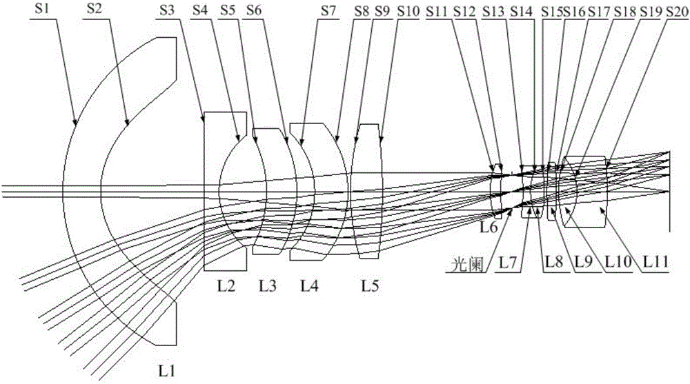
[0037] Table 1 shows the structural parameters of the space target imaging optical system

[0038]

[0039]

[0040] In Table 1, S1 is the left surface of the first lens L1; S2 is the right surface of the first lens L1; S3 is the left surface of the second lens L2; ​​S4 is the right surface of the second lens L2; ​​S5 is the third lens L3 S6 is the right surface of the third lens L3; S7 is the left surface of the fourth lens L4; S8 is the right surface of the fourth lens L4; S9 is the left surface of the fifth lens L5; S10 is the fifth lens L5 S11 is the left surface of the sixth lens L6; S12 is the right surface of the sixth lens L6; S13 is the left surface of the seventh lens L7; S14 is the right surface of the seventh lens L7, also the eighth lens L8 S15 is the right surface of the eighth lens L8; S16 is the left surface of the ninth lens L9; S17 is the right surface of the ninth lens L9; S18 is the left surface of the tenth lens L10; S19 is the tenth lens L10 The ri...


PUM


Abstract

The invention discloses a space object imaging optical system, which belongs to the technical field of space imaging. The technical problems of many moving parts, poor reliability, large quality and cumbersome structure in the space target imaging optical system in the prior art are solved. The optical system of the present invention includes a first lens, a first lens group, a diaphragm and a second lens group arranged in sequence along the same optical axis from left to right, wherein the left surface of the first lens is a spherical surface, and the right surface is a high-order lens. Aspheric surface, the material of the first lens is fused silica; the aspheric coefficient of the high-order aspheric surface satisfies the following formula: where: z is the sagittal height of the lens in the direction of the optical axis, c is the vertex curvature, k is the conic constant, y is the axial distance, at least one of the aspheric coefficients D, E, F, G is not zero. Under the premise of ensuring a large field of view, the optical system of the present invention has a large relative aperture, small distortion value, strong system reliability, small volume and light weight.

Description

technical field [0001] The invention provides a space object imaging optical system, which belongs to the technical field of space imaging. Background technique [0002] The small field of view space target imaging optical system has the problem of small imaging range, so it is necessary to expand its target imaging range. In the prior art, the target imaging range is usually expanded by adding a front scanning mirror. Although this system can expand the target imaging range, due to the addition of the front scanning mirror, the system has many moving parts and poor reliability. [0003] In addition, the working environment of the space target imaging optical system is harsh, and it is vulnerable to shock and vibration, which will cause the internal optical components of the optical system to heat up, resulting in poor imaging quality. In the prior art, this problem is usually solved by setting an additional protective window in front of the optical system for passive therm...

Claims


Application Information

Patent Timeline
Patent Type & Authority Patents(China)
IPC IPC(8): G02B13/00G02B13/06G02B13/04G02B13/18G02B1/00G02B27/00
Inventor 孟庆宇纪振华董吉洪王维
Owner CHANGCHUN INST OF OPTICS FINE MECHANICS & PHYSICS CHINESE ACAD OF SCI
Learn More