
Dry pipe valve for fire protection sprinkler system

a technology of sprinkler system and dry pipe, which is applied in the direction of service pipe system, functional valve type, valve operation means/release devices, etc., can solve the problems of large and heavy valve, difficult installation, and more components, and achieve the effect of reducing weight, reducing installation difficulty, and reducing maintenance costs

Inactive Publication Date: 2008-01-29
JOHNSON CONTROLS TYCO IP HLDG LLP
View PDF23 Cites 24 Cited by
  • Summary
  • Abstract
  • Description
  • Claims
  • Application Information

AI Technical Summary

Benefits of technology

The invention is a differential-type dry pipe valve for a fire protection sprinkler system that has a ratio of effective air sealing area to service water sealing area that is smaller than a ratio of service water pressure to system air pressure at which the fire protection sprinkler system is actuated. The valve has a water valve seat and an air valve seat that are off-center relative to each other. The valve also has a clapper that can be opened and closed to control the flow of water through the valve. The valve has a simple construction, with few moving parts, and is compact and lightweight compared to prior art valves of similar specification.

Problems solved by technology

This valve design is very reliable and made from relatively few parts; however, this relationship also results in a valve that is relatively large and heavy, and therefore difficult to install.
This type of dry pipe valve is relatively smaller in size, but it requires more components, and it is often more difficult to maintain because of the relatively greater number of parts located within its auxiliary chamber.

Method used


Image

  • Dry pipe valve for fire protection sprinkler system
  • Dry pipe valve for fire protection sprinkler system
  • Dry pipe valve for fire protection sprinkler system

Examples


Embodiment Construction

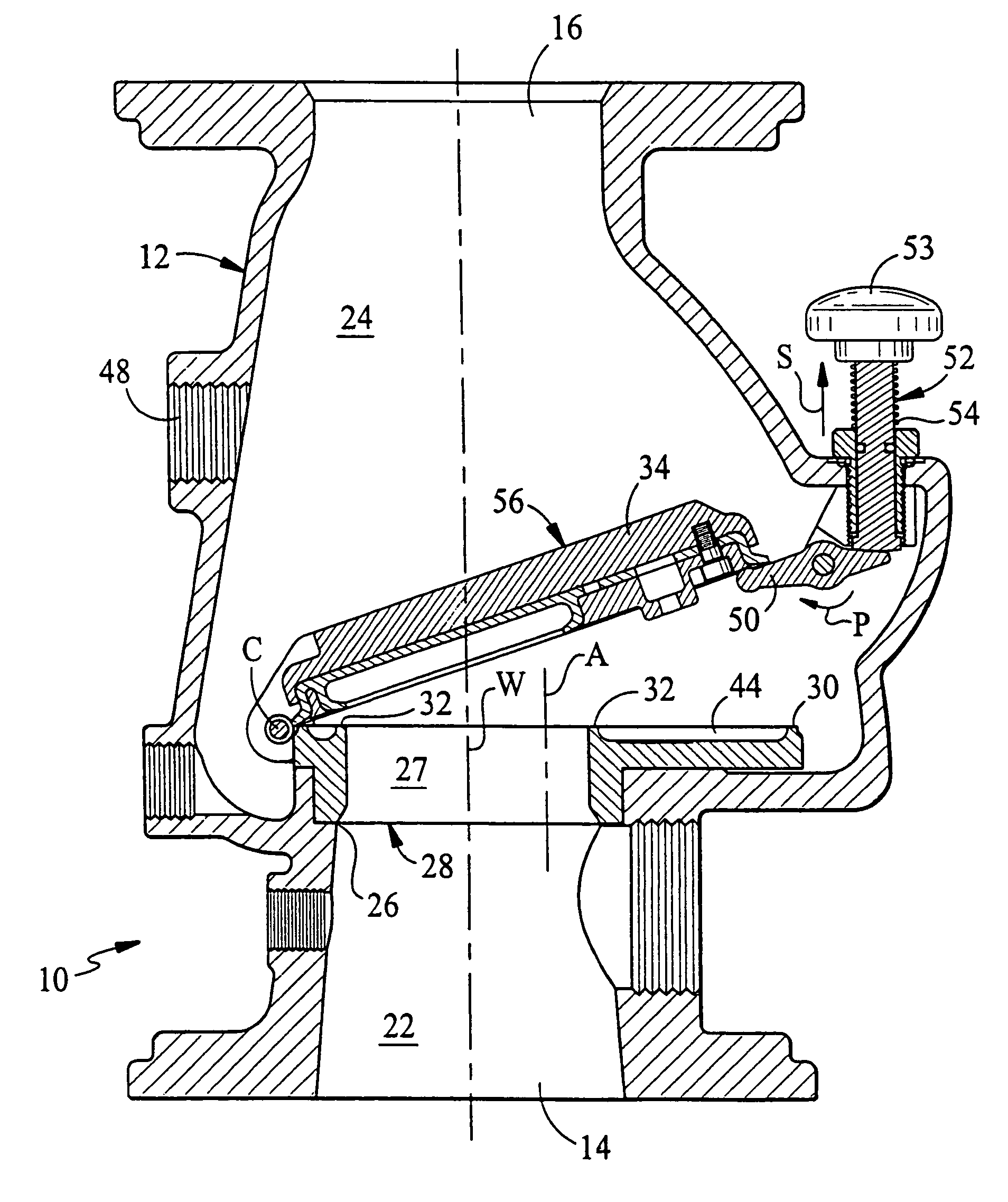
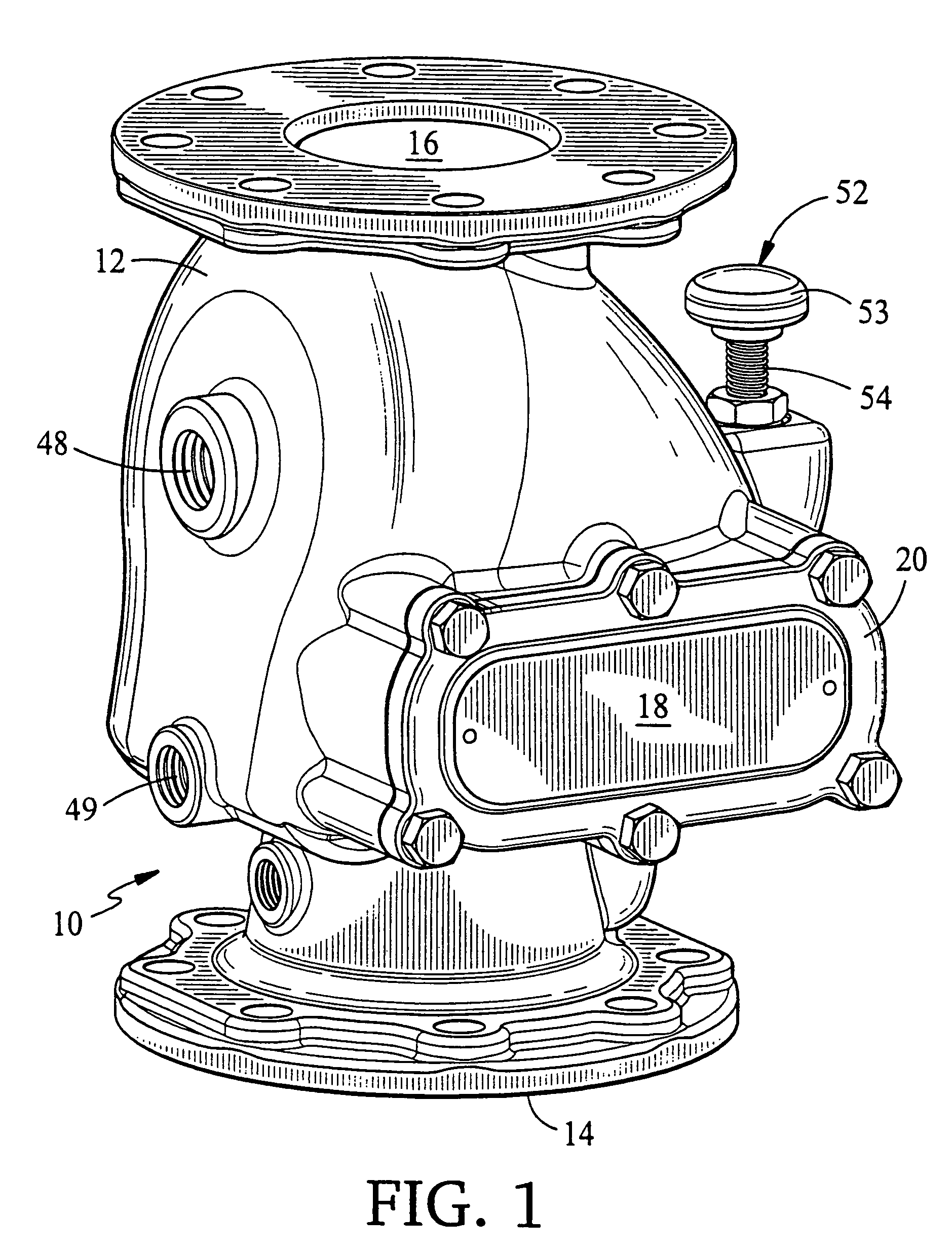
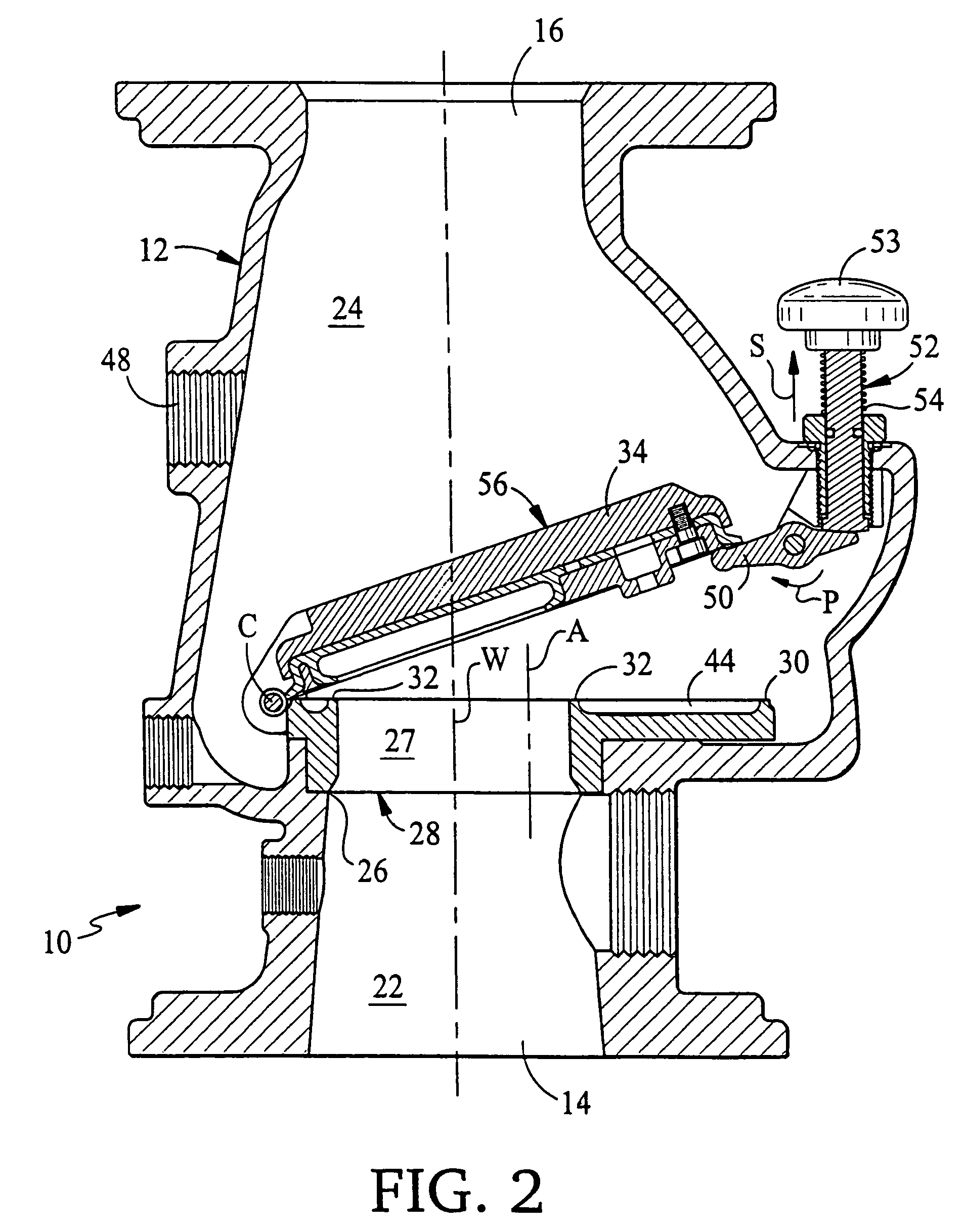
[0044]Referring to FIGS. 1–5, a differential-type dry pipe valve 10 of the invention, for use in an automatic fire protection sprinkler system, has a body 12 defining an inlet 14 and an outlet 16, and a valve access port 18 (FIG. 4) secured by a cover 20. The body 12 further defines a water-side chamber 22 in communication with inlet 14, and an air-side chamber 24 in communication with the outlet 16. Referring also to FIGS. 6–9, a seat body 28, defining a passageway 27 surrounded by an air valve seat 30 and a water valve seat 32, is disposed in an aperture 26 defined by the body 12 between the water-side chamber 22 and the air-side chamber 24. Referring in addition to FIGS. 10–14, a single clapper 34 is mounted between ears 36, 37 of the seat body 28 to pivot about an axis, C (FIG. 2), which is closely adjacent and tangential to the air valve seat 30. Referring finally to FIGS. 15–19 and FIGS. 20–23, a clapper diaphragm 38, mounted to the clapper 34 by clapper diaphragm retaining pl...


PUM


Abstract

A fire protection system comprises a supply pipe having a first fluid pressurized to a first pressure and a network of pipes having a plurality of sprinklers. The network of pipes have a second fluid being pressurized to a second pressure at approximately 5.5 times the first pressure. The system further comprises a dry pipe valve including a body defining a passage extending along a longitudinal axis between an inlet coupled to the supply pipe and an outlet coupled to the network of pipes. The inlet has an inlet diameter of approximately WD inches and a seat disposed in the body has a seating surface with a diameter AD approximately less than two times WD inches. The dry pipe valve further includes a clapper pivotable about an axis orthogonal to the longitudinal axis between a first position occluding the passage when the ratio of the second pressure to the first pressure is at least 5.5 and a second position permitting fluid flow through the passage when the ratio is less than 5.5.

Description

RELATED APPLICATIONS[0001]This divisional application claims the benefit under 35 U.S.C. §§ 120 and 121 of original application Ser. No. 10 / 715,422 filed on Nov. 19, 2003, now U.S. Pat. No. 7,104,333 which is a divisional application of 10 / 391,657 filed on Mar. 20, 2003, now U.S. Pat. No. 6,810,963, which is a continuation of application Ser. No. 09 / 593,101 filed on Jun. 13, 2000, now U.S. Pat. No. 6,557,645. This application claims the right of priority to each of the prior applications. Furthermore, each of the prior applications is hereby incorporated by reference in its entirety into this divisional application.TECHNICAL FIELD[0002]This invention relates to dry pipe automatic fire protection sprinkler systems.BACKGROUND OF THE INVENTION[0003]Dry pipe automatic fire protection sprinkler systems are typically employed for the purpose of providing automatic sprinkler protection in unheated occupancies and structures that may be exposed to freezing temperatures. The dry pipe sprinkl...

Claims


Application Information

Patent Timeline
Patent Type & Authority Patents(United States)
IPC IPC(8): A62C35/00A62C35/62A62C35/68F16K1/20
CPCA62C35/62A62C35/68F16K15/03F16K17/386Y10T137/7866Y10T137/0491Y10T137/7877Y10T137/7903Y10T137/0379Y10T137/8359F16K15/1821
Inventor RINGER, YORAM
Owner JOHNSON CONTROLS TYCO IP HLDG LLP
Learn More