
A circuit board wiring method and system

A wiring method and circuit board technology, applied in the direction of electrical digital data processing, special data processing applications, instruments, etc., can solve the problems of low wiring efficiency and achieve the effect of improving efficiency and reducing workload

Active Publication Date: 2018-03-02
湖州帷幄知识产权运营有限公司
View PDF4 Cites 0 Cited by
  • Summary
  • Abstract
  • Description
  • Claims
  • Application Information

AI Technical Summary

Problems solved by technology

[0005] In view of the above-mentioned shortcomings of the prior art, the purpose of the present invention is to provide a circuit board wiring method and system, which is used to solve the problem of low wiring efficiency due to the need for a lot of repeated wiring work in the prior art circuit board wiring. The problem

Method used


Image

  • A circuit board wiring method and system
  • A circuit board wiring method and system
  • A circuit board wiring method and system

Examples


no. 1 example

[0036] This embodiment provides a circuit board wiring method, which is applied to the wiring of multiple circuit boards with at least two identical chips. Generally, the wiring of the CPU and peripheral ICs of the same intelligent platform are the same, so when a After the circuit boards are wired, the second, third and other circuit boards of the same intelligent platform can be quickly and efficiently wired according to the method of this embodiment.

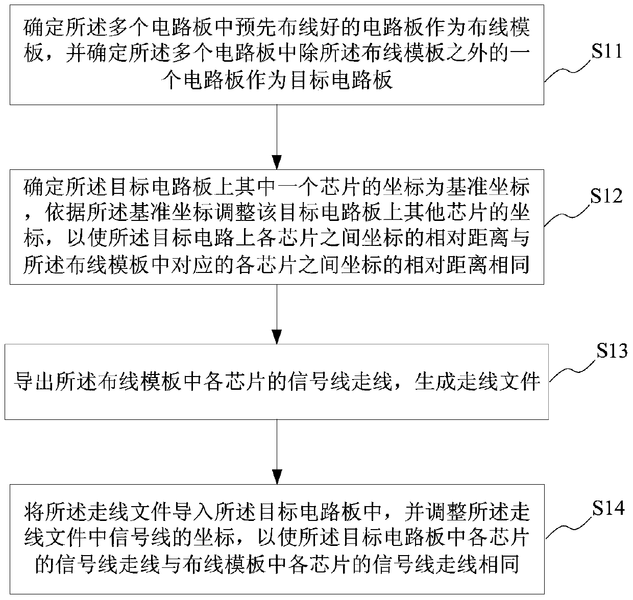
[0037] Such as figure 1 As shown, the wiring method includes the following steps:

[0038] Step S11 , determining a pre-wired circuit board among the plurality of circuit boards as a wiring template, and determining a circuit board among the plurality of circuit boards other than the wiring template as a target circuit board.

[0039] Step S12, determining the coordinates of one of the chips on the target circuit board as the reference coordinates, adjusting the coordinates of other chips on the target circuit board accordin...

no. 2 example

[0058] In order to realize the above circuit board wiring method, this embodiment provides a corresponding circuit board wiring system, please refer to Figure 4 , which is a schematic structural diagram of a circuit board wiring system of the present invention. Such as Figure 4 and Figure 5 As shown, this embodiment provides a circuit board wiring system, which is applied to the wiring of multiple circuit boards with at least two identical chips. Generally, the wiring of the CPU and peripheral ICs of the same intelligent platform are the same, so when After the wiring of one circuit board is laid out, the wiring of the second, third and other circuit boards of the same intelligent platform can be quickly and efficiently carried out according to the wiring system of this embodiment.

[0059] Such as Figure 4 As shown, the circuit board wiring system 1 in this embodiment includes: a wiring template 11 , a wiring file module 12 and a wiring module 13 .

[0060] The wiring...


PUM


Abstract

The present invention provides a circuit board wiring method and system, which are applied to the wiring of multiple circuit boards with at least two identical chips. The method includes: determining a pre-wired circuit board among the multiple circuit boards as a wiring template, And determine a circuit board other than the wiring template in the multiple circuit boards as the target circuit board; determine the coordinates of one of the chips on the target circuit board as the reference coordinates, adjust the coordinates of other chips according to the reference coordinates, so that each on the target circuit The relative distance of the coordinates between the chips is the same as the relative distance of the coordinates between the corresponding chips in the wiring template; export the signal line routing of each chip in the wiring template, and generate a routing file; import the routing file into the target circuit board, And adjust the coordinates of the signal lines in the routing file, so that the routing of each chip in the target circuit board is the same as that of each chip in the wiring template. The invention greatly reduces the workload of circuit board wiring and effectively improves the efficiency of circuit board wiring work.

Description

technical field [0001] The invention relates to the technical field of circuit board wiring, in particular to a circuit board wiring method and system. Background technique [0002] In the entire information, communication and consumer electronics products, the printed circuit board (Printed Circuit Board, PCB) is an indispensable basic component. The printed circuit board can connect the electronic parts together and provide the mutual current connection of each electronic part. , and as electronic equipment becomes more and more complex, more and more parts need to be installed on the circuit board, and the lines on the circuit board tend to be denser, therefore, great challenges arise in circuit board wiring. [0003] At present, the more common method of circuit board layout (Layout) is the combination of software program automatic wiring and manual wiring. Among them, the use of software program automatic wiring has the characteristics of fast completion speed and high ...

Claims


Application Information

Patent Timeline
Patent Type & Authority Patents(China)
IPC IPC(8): G06F17/50
Inventor 王波
Owner 湖州帷幄知识产权运营有限公司
Learn More