
A Resistor for Condensing High-power Automobiles with New Lead Structure

A lead-out structure and high-power technology, applied in the direction of resistors, adjustable resistors, other resistor networks, etc., can solve problems such as the separation of the root of the wire harness from the insulation layer, the exposure of metal wires, and the reduction of insulation, so as to improve reliability. Effects of safety, guarantee of airtightness, and improvement of stability

Active Publication Date: 2016-09-14
上海克拉电子有限公司
View PDF6 Cites 0 Cited by
  • Summary
  • Abstract
  • Description
  • Claims
  • Application Information

AI Technical Summary

Problems solved by technology

For systems that require high-power single fans, the existing speed-regulating resistor technology cannot meet the requirements of high-current and long-term operation in high-temperature environments
Although the spring type speed regulating resistor of the prior art can work under high current, it is used by more and more porcelain skeleton resistors because of its high operating temperature, instability when overheated, and low reliability of protection during abnormal operation. replace
However, the existing porcelain skeleton condensation resistors are mostly used for speed regulation of small-power fans, and the existing resistors for high-power single-fan systems cannot meet the requirements of high-current and long-term operation in high-temperature environments.
The lead-out structure of the speed-regulating resistor in the prior art is the direct lead-out of the wire harness. In some installation situations where the wire harness needs to be bent, it is easy to cause the root of the wire harness to separate from the insulation layer, and the metal wire is exposed, resulting in the risk of reduced airtightness and insulation.

Method used


Image

  • A Resistor for Condensing High-power Automobiles with New Lead Structure
  • A Resistor for Condensing High-power Automobiles with New Lead Structure
  • A Resistor for Condensing High-power Automobiles with New Lead Structure

Examples


Embodiment

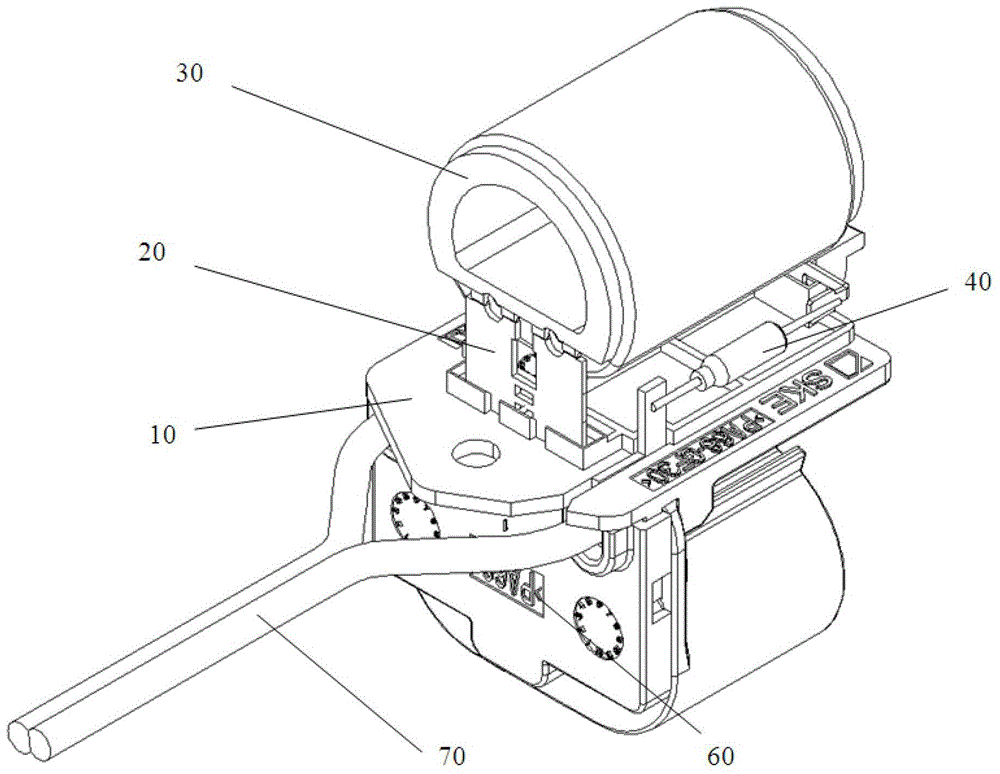
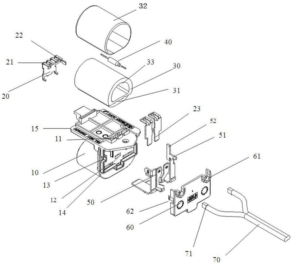
[0023] Such as Figure 2-3 As shown, a high-power automotive condensing resistor with a new structure includes a base 10, a connecting bracket 20, a resistance assembly 30, a temperature fuse 40, pins 50, a rear cover 60 and a wiring harness 70, and the connecting bracket 20 and the rear cover 60 are installed on the base 10, the resistance assembly 30 is fixed on the connection bracket 20, one end of the thermal fuse 40 is connected to the connection bracket 20, and the other end is connected to the pin 50, and the connection bracket 20 is connected to the pin 50 , and the wire harness 70 is connected to the pin 50 after passing through the rear cover 60 .

[0024] The base 10 includes a base plate 15 and a connector housing located at the bottom of the base plate 15, the base plate 15 is provided with a plurality of bracket slots 11; the rear side of the connector housing is provided with a pin mounting area 12. The pin mounting area 12 is provided with a plurality of pin s...


PUM


Abstract

The invention relates to a large-power automobile condensation resistor having a novel extraction structure. The large-power automobile condensation resistor comprises a pedestal (10), a connection support (20), a resistor assembly (30), a temperature fuse (40), a pin (50) and a wiring harness (70). The large-power automobile condensation resistor also comprises a rear cover plate (60). The connection support (20) and the rear cover plate (60) are installed on the pedestal (10). The resistor assembly (30) is fixed to the connection support (20). One end of the temperature fuse (40) is connected to the connection support (20), and the other end of the temperature fuse (40) is connected to the pins (50). The connection support (20) is connected to the pin (50). The wiring harness (70) goes through the rear cover plate (60) and then is connected to the pin (50). Compared with the prior art, the large-power automobile condensation resistor has the advantages of wide application range, good stability, high safety and long service life.

Description

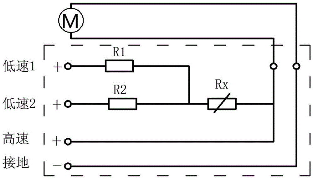
technical field [0001] The invention relates to a resistor, in particular to a high-power automotive condensation resistor with a new lead-out structure. Background technique [0002] Such as figure 1 As shown, the existing automotive condensing resistors are mainly composed of two parts in function, one part is several fixed resistors, and the other part is a temperature protection device. Both the resistor and the temperature protection device are connected in series to the automotive condensation fan circuit. The partial pressure effect reduces the current passing through the fan motor, thereby reducing the motor speed; the main function of the temperature protection device is to cut off the circuit in time to protect peripheral components when the car circuit is abnormal and the resistance is overheated. In the vehicle condensing fan system, through automatic switching, the system connects one or more resistance values ​​in the speed regulating resistor in series or dis...

Claims


Application Information

Patent Timeline
Patent Type & Authority Patents(China)
IPC IPC(8): H01C10/00H01C10/16H01C1/01H01C1/14H01C1/16
Inventor 骆晶晶
Owner 上海克拉电子有限公司
Learn More