Field emission display screen

A technology of display screen and field emission, which is applied in the direction of image/graphic display tube, cathode ray tube/electron beam tube, discharge tube, etc., which can solve the problems of high maintenance cost, PCB board damage, inconvenient maintenance, etc.

Inactive Publication Date: 2014-08-06
OCEANS KING LIGHTING SCI&TECH CO LTD +2
View PDF5 Cites 0 Cited by
  • Summary
  • Abstract
  • Description
  • Claims
  • Application Information

AI Technical Summary

Problems solved by technology

When a single pixel is damaged, the solder joint of the damaged pixel must be melted and removed first, and then a new pixel is soldered on the PCB, which makes mai

Method used


Image

  • Field emission display screen
  • Field emission display screen
  • Field emission display screen

Examples


Embodiment Construction

[0024] In order to facilitate the understanding of the present invention, the present invention will be described more fully below with reference to the associated drawings. Preferred embodiments of the invention are shown in the accompanying drawings. However, the present invention can be embodied in many different forms and is not limited to the embodiments described herein. On the contrary, these embodiments are provided to make the understanding of the disclosure of the present invention more thorough and comprehensive.

[0025] It should be noted that when an element is referred to as being “fixed” to another element, it can be directly on the other element or there can also be an intervening element. When an element is referred to as being "connected to" another element, it can be directly connected to the other element or intervening elements may also be present.

[0026] Unless otherwise defined, all technical and scientific terms used herein have the same meaning as...


PUM


Abstract

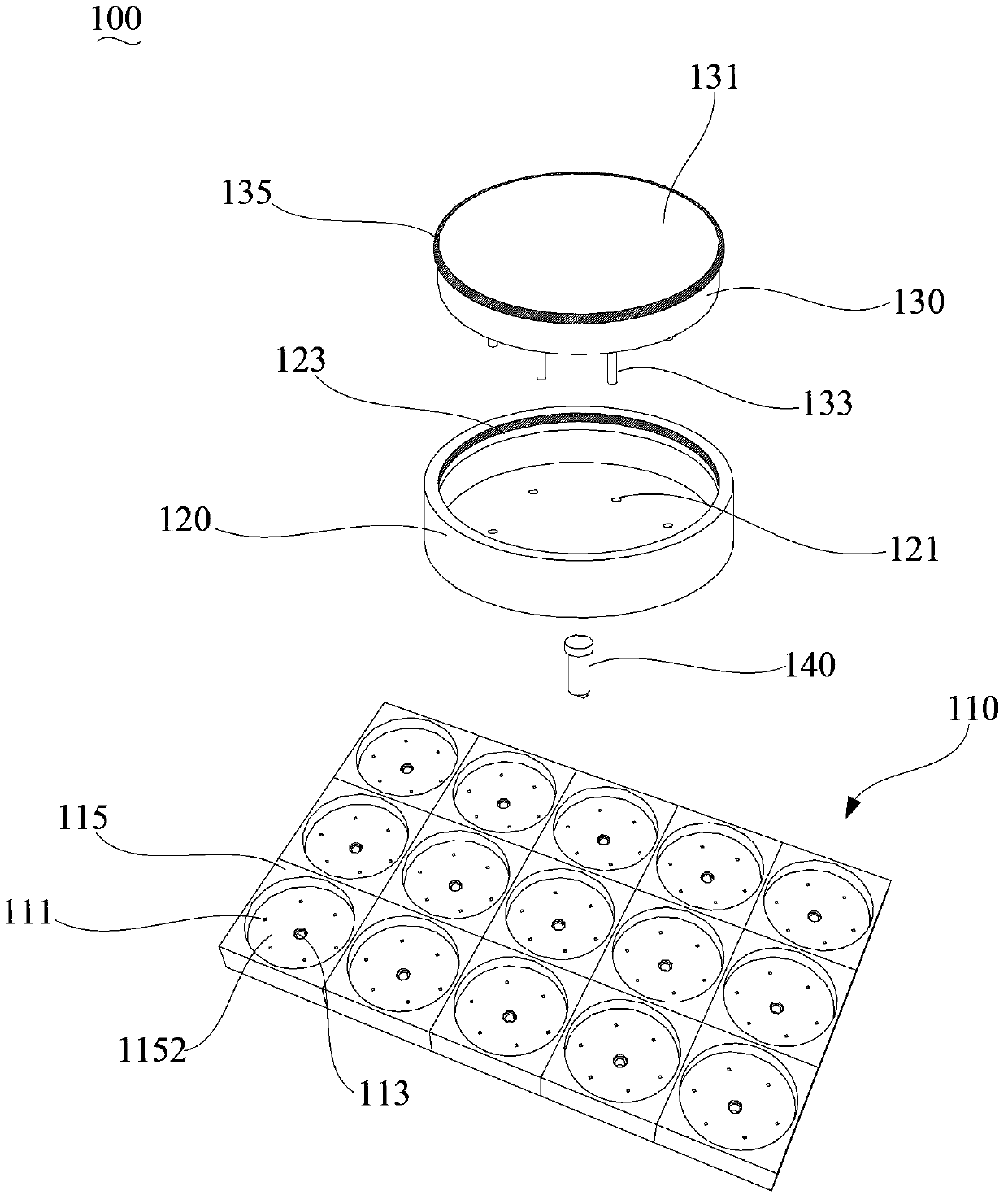
The invention provides a field emission display screen which comprises a PCB, supporting bodies and pixel modules. The pixel modules are installed on the PCB through the supporting bodies. A light-emitting body is electrically connected with a drive circuit of the PCB through matching of a pin and a pin socket instead of being directly welded to the PCB. When a certain pixel module is damaged, only the supporting bodies need to be separated from the PCB at first, the pin is pulled out from the pin socket, a new pixel module is reinstalled, and welding is not needed; moreover, when the damaged pixel module is replaced, welding operation can be avoided, and therefore the PCB can be prevented from being damaged by excessively high temperature in the welding process; the field emission display screen is more convenient to maintain and low in maintenance cost.

Description

technical field [0001] The invention relates to display technology, in particular to a field emission display screen. Background technique [0002] Field electron emission, also known as cold electron emission, only needs to apply a strong electric field on the surface of the cathode without any additional energy, so that the electrons in the cathode can have enough energy to escape from the surface. An important application of field electron emission is the field emission display. The field emission display screen uses field emission technology as the electron source to replace the thermal electron gun in the traditional CRT picture tube. Because it does not use thermal energy, the energy distribution range of the field emission electron beam is narrower than that of the traditional electron beam. Moreover, the field emission display has the best display quality such as high brightness, high contrast, high resolution, and pure color reproduction. At the same time, field e...

Claims


Application Information

Patent Timeline
IPC IPC(8): H01J31/12H01J29/02
Inventor 周明杰梁艳馨徐习贤陈贵堂
Owner OCEANS KING LIGHTING SCI&TECH CO LTD
Why Eureka
Try Eureka