Flexible electronic device

An electronic device and flexible technology, applied in display devices, identification devices, circuits, etc., can solve problems such as stress interference, carrier board wrinkles, stress creep, etc., and achieve the effect of reducing the degree of stress concentration

Inactive Publication Date: 2014-08-06
IND TECH RES INST
View PDF11 Cites 17 Cited by
  • Summary
  • Abstract
  • Description
  • Claims
  • Application Information

AI Technical Summary

Problems solved by technology

[0003] However, when the flexible electronic device is flexed, the stress will concentrate on the bends of the folded or deflected carrier board during assembly, resulting in stress interference, stress creep, carrier board buckling, local deformation or signal contact (such as the external terminal area) is destroyed, etc.

Method used


Image

  • Flexible electronic device
  • Flexible electronic device
  • Flexible electronic device

Examples


Embodiment Construction

[0052] Below in conjunction with accompanying drawing, structural principle and working principle of the present invention are specifically described:

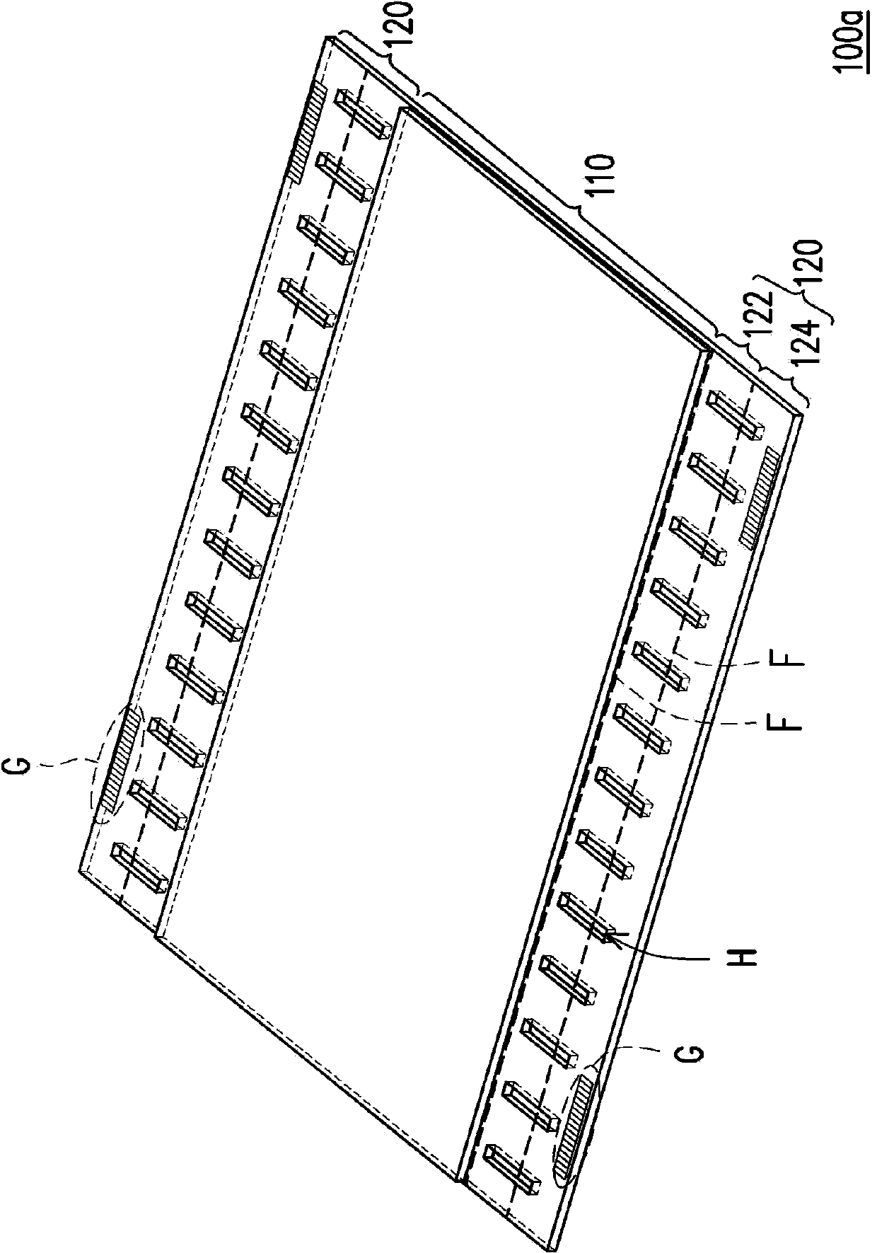
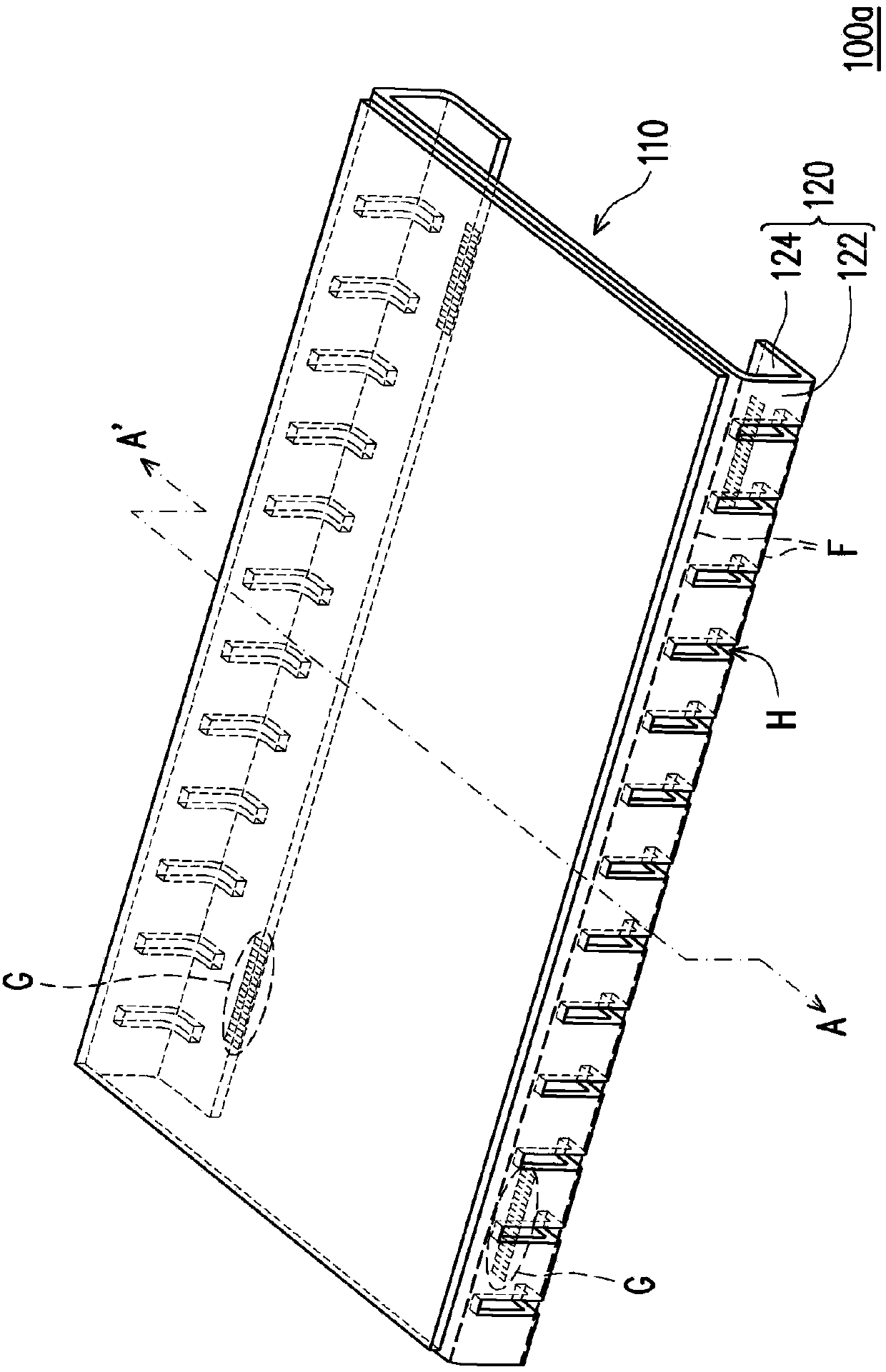
[0053] figure 1 It is an unfolded schematic diagram of a flexible electronic device according to an embodiment of the present invention. figure 2 for figure 1 A perspective side view of a flexible electronic device. Please refer to figure 1 with figure 2 , the flexible electronic device 100 a includes an element portion 110 and at least one bending portion 120 , wherein the bending portion 120 is connected to the element portion 110 .

[0054] The flexible electronic device 100a is, for example, formed by arranging electronic components on a flexible substrate. The present invention does not particularly limit the type of the flexible electronic device 100a. For example, the flexible electronic device 100a may be a flexible display device, and in this case, the element part 110 may be an organic light emitting element,...


PUM


Abstract

A flexible electronic device of the disclosure may include a component portion and at least one folded portion connected to the component portion, wherein the flexible electronic device has a plurality of flexed lines located on the single folded portion and a plurality of stress relief holes, the stress relief holes are separated from each other, and at least a part of the stress relief holes is located on at least one of the flexed lines.

Description

technical field [0001] The invention relates to an electronic component, and in particular to a flexible electronic device. Background technique [0002] Flexible electronic devices are bound to become the mainstream of the next generation due to their characteristics of thinness, flexibility, impact resistance, high safety, and portability. Due to the design requirements of narrow margins or signal conduction, the carrier board used to carry electronic components in flexible electronic devices is often folded or bent during assembly. [0003] However, when the flexible electronic device is flexed, the stress will concentrate on the bends of the folded or deflected carrier board during assembly, resulting in stress interference, stress creep, carrier board buckling, local deformation or signal contact (such as the external terminal area) is destroyed and so on. Therefore, how to take into account the narrowing of the margin and solving the problem of stress concentration a...

Claims


Application Information

Patent Timeline
Patent Type & Authority Applications(China)
IPC IPC(8): H01L27/32
CPCH05K2201/09063H05K1/189H05K2201/10106H05K1/028G09F13/22G09F9/00H05K2201/10128G09F9/33
Inventor 彭懿正何长安
Owner IND TECH RES INST
Why Eureka
Try Eureka