Angle adjustable type wire end ground clamp

A grounding clip, adjustable technology, applied in the direction of clip connection conductor connection, electrical connection seat, overhead line/cable equipment, etc., can solve the problems of low efficiency, high labor intensity, difficult operation, etc. The effect of reducing labor intensity and reducing the number of spiral turns

Inactive Publication Date: 2014-08-06
GUANGXI UNIV
View PDF6 Cites 18 Cited by
  • Summary
  • Abstract
  • Description
  • Claims
  • Application Information

AI Technical Summary

Problems solved by technology

However, for the 500kV line, the first three types of clip structures are not reasonable, and they are easy to fall off, making the working point lose protection
Although the spiral type can ensure reliable ground

Method used


Image

  • Angle adjustable type wire end ground clamp
  • Angle adjustable type wire end ground clamp
  • Angle adjustable type wire end ground clamp

Examples


Embodiment Construction

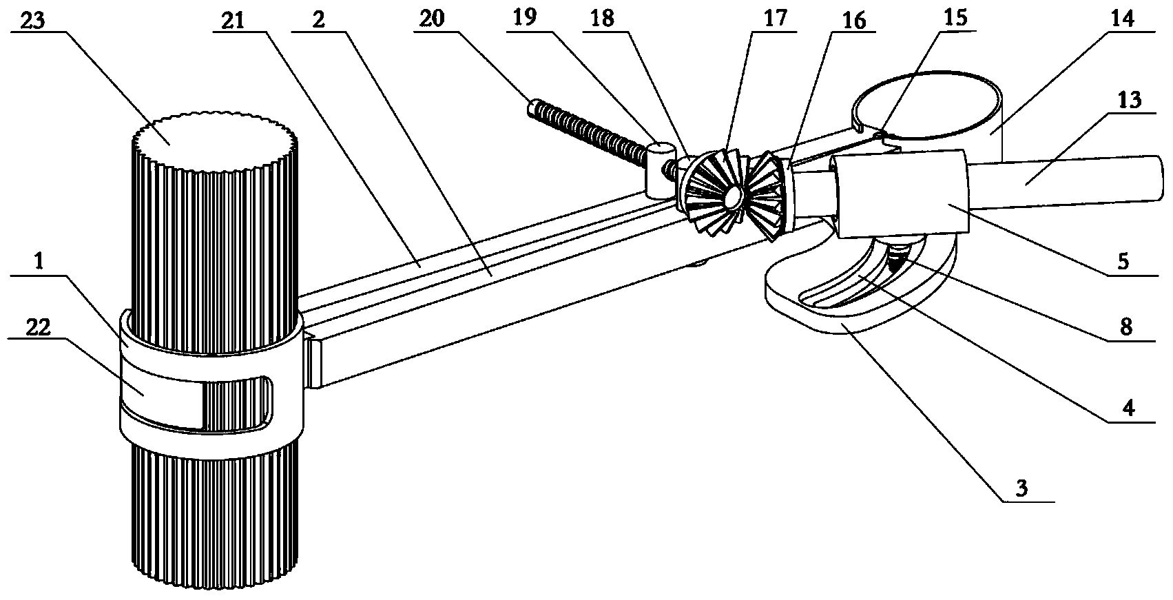
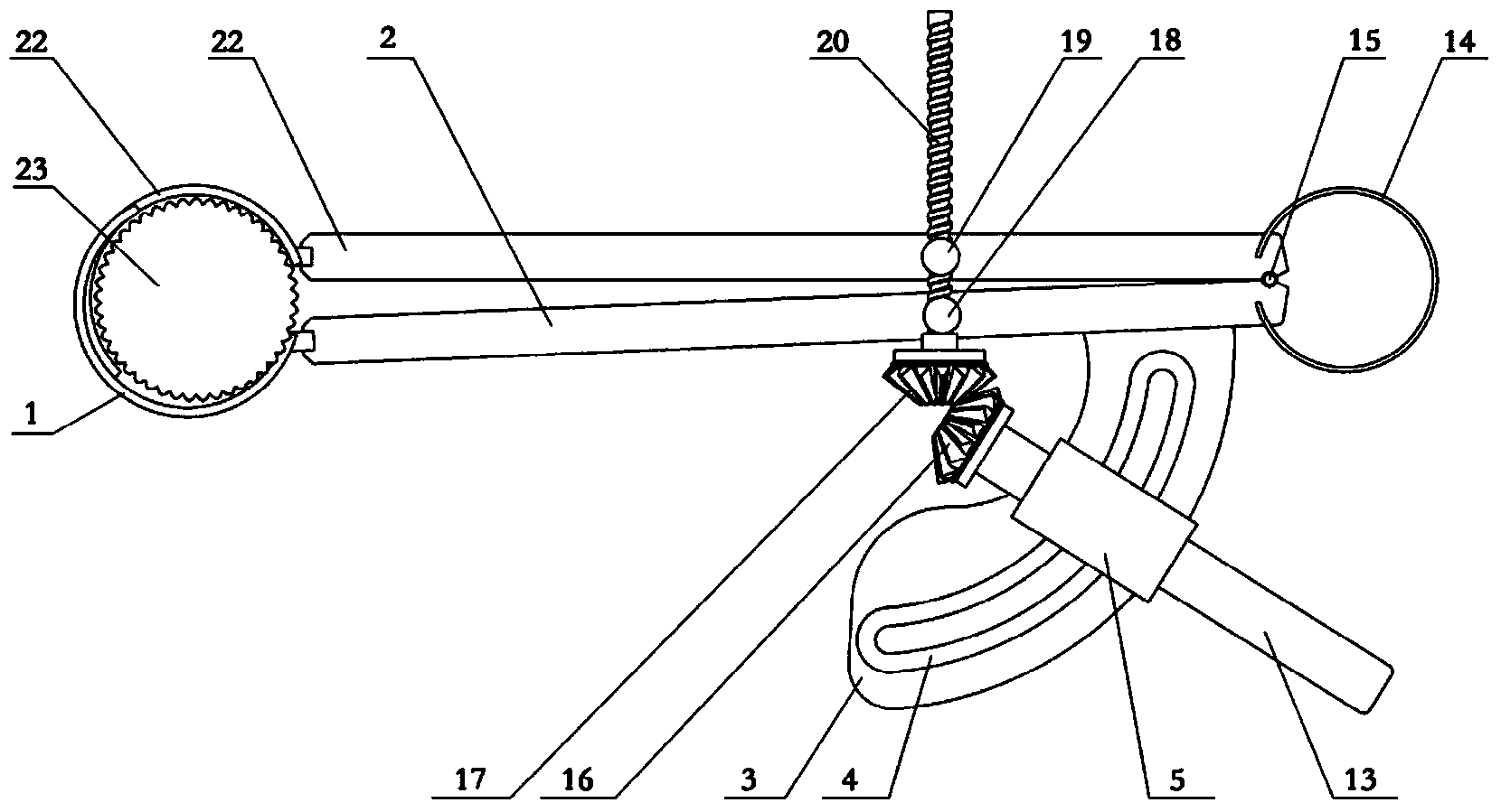
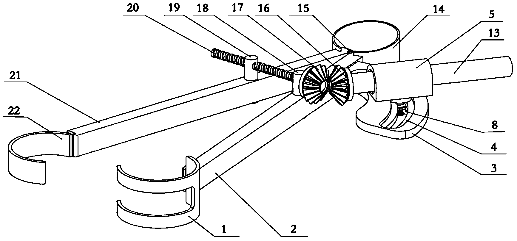
[0020] Such as Figure 1 to Figure 7 As shown, the angle-adjustable wire end grounding clamp of the present invention includes a clamp main body, a transmission mechanism, an angle adjustment mechanism and a joystick 13 . The main line clamp body 2 and the secondary line clamp body 21 of the clamp body are positioned by the spring collar 14 and the first hinge point 15, and the other ends of the main line clamp body 2 and the secondary line clamp body 21 are respectively the main line chuck 1 and the secondary line clamp The head 22, the main line clip body 2 near the spring collar 14 is a fan-shaped plate 3 with a central angle of 90 degrees. The fan-shaped plate 3 is provided with a circular arc limit groove 4, and the bottom is provided with a ground wire connector. The ground wire connector includes a gasket 10. Nuts 11, ground wire joint bolts 12, the main line clamp body 2 near the fan-shaped plate 3 is the second hinge point 18 with a through hole in the middle; the aux...


PUM


Abstract

An angle adjustable type wire end ground clamp comprises a clamp body, a transmission mechanism, an angle adjusting mechanism and an operating rod. By combining and utilizing the operating rod, a straight tooth bevel gear wheel and the thread transmission mechanism, the purposes of decreasing the number of spiral coils and relieving the labor intensity are achieved by enlarging the stroke of a chuck of the clamp. The chuck can be opened and closed only by rotating the operating rod, so that a high-tension cable is clamped and released rapidly. The angle adjustable type wire end ground clamp solves the problems that a traditional clamp mechanism is complex in structure and not firm in clamping, so that construction operation is easier, safer and more convenient, workloads of detection personnel can be effectively lowered, and safety is improved. In addition, the requirement for the adjustable angle between the clamp and the operating rod is met through an angle adjusting and locking bolt and an arc limit groove of a sector plate.

Description

technical field [0001] The invention relates to a tool for overhauling high-voltage wires, in particular to an angle-adjustable wire end grounding clip. Background technique [0002] The grounding clamp at the wire end is a safety device used to temporarily short-circuit and ground the power-off transmission wire. Its function is to prevent the harm to the human body caused by the sudden incoming power or the induced voltage generated by the adjacent high-voltage live equipment during the maintenance of the high-voltage transmission wire. At present, the clamps used by various power grid companies mainly include double tongue type, flat type, impact type and spiral type. However, for the 500kV line, the first three types of clip structures are not reasonable, and they are easy to fall off, making the working point lose protection. Although the spiral type can ensure reliable grounding, the use of it is labor-intensive, inefficient, and difficult to operate, and it is easy t...

Claims


Application Information

Patent Timeline
IPC IPC(8): H01R11/26H01R43/027H02G1/02
Inventor 郑广平朱立靖覃海英卢煜海苏文桂黄宝岚谢少坚
Owner GUANGXI UNIV
Why Eureka
Try Eureka