Locking method for preventing motor from being switched into short-circuit fault

A technology for short-circuit faults and electric motors, applied in circuit devices, emergency protection circuit devices, electrical components, etc., can solve the problems of expanding accidents, low voltage of power supply system, frequent starting, etc., and achieve the effect of preventing accidents from expanding and ensuring safe operation

Inactive Publication Date: 2014-08-06
BAOSTEEL STAINLESS STEEL
View PDF1 Cites 1 Cited by
  • Summary
  • Abstract
  • Description
  • Claims
  • Application Information

AI Technical Summary

Problems solved by technology

However, the disadvantage of this control method is that the control power of the motor is taken from the primary power supply circuit of the motor. Once a "low voltage" event occurs in the power supply system, it will cause the motor to stop. When the voltage of the power supply system fluctuates, it will even cause the motor to start frequently. It is easy to cause equipment damage, and also affect the continuity of production, bringing huge economic losses to factories and enterprises
[0009] In order to solve the above problems, factories and enterprises adopt control power supply improvement methods for motors of some important production units to ensure that when low voltage occurs in the power supply system, the control power supply of important motors remains stable, and operates normally when the power supply "power failure" and "standby self-switching" After switching, the motor can be started and run continuously. However, the disadvantage of this method is that once the power supply self-switching lock fails, and the power supply is accidentally switched to a "short-circuit" fault, the motor control circuit power supply will be stable and the contactor will not work. It will be released without pressure, causing the motor and the primary power supply system to still be connected together. Even if the motor body protection works effectively, it is very easy to cause the motor insulation to be damaged, or even burned, causing low voltage in the power supply system, expanding the accident, and bringing more damage to the enterprise. big economic loss

Method used


Image

  • Locking method for preventing motor from being switched into short-circuit fault
  • Locking method for preventing motor from being switched into short-circuit fault
  • Locking method for preventing motor from being switched into short-circuit fault

Examples


Embodiment Construction

[0033] The present invention will be further described below in conjunction with the accompanying drawings.

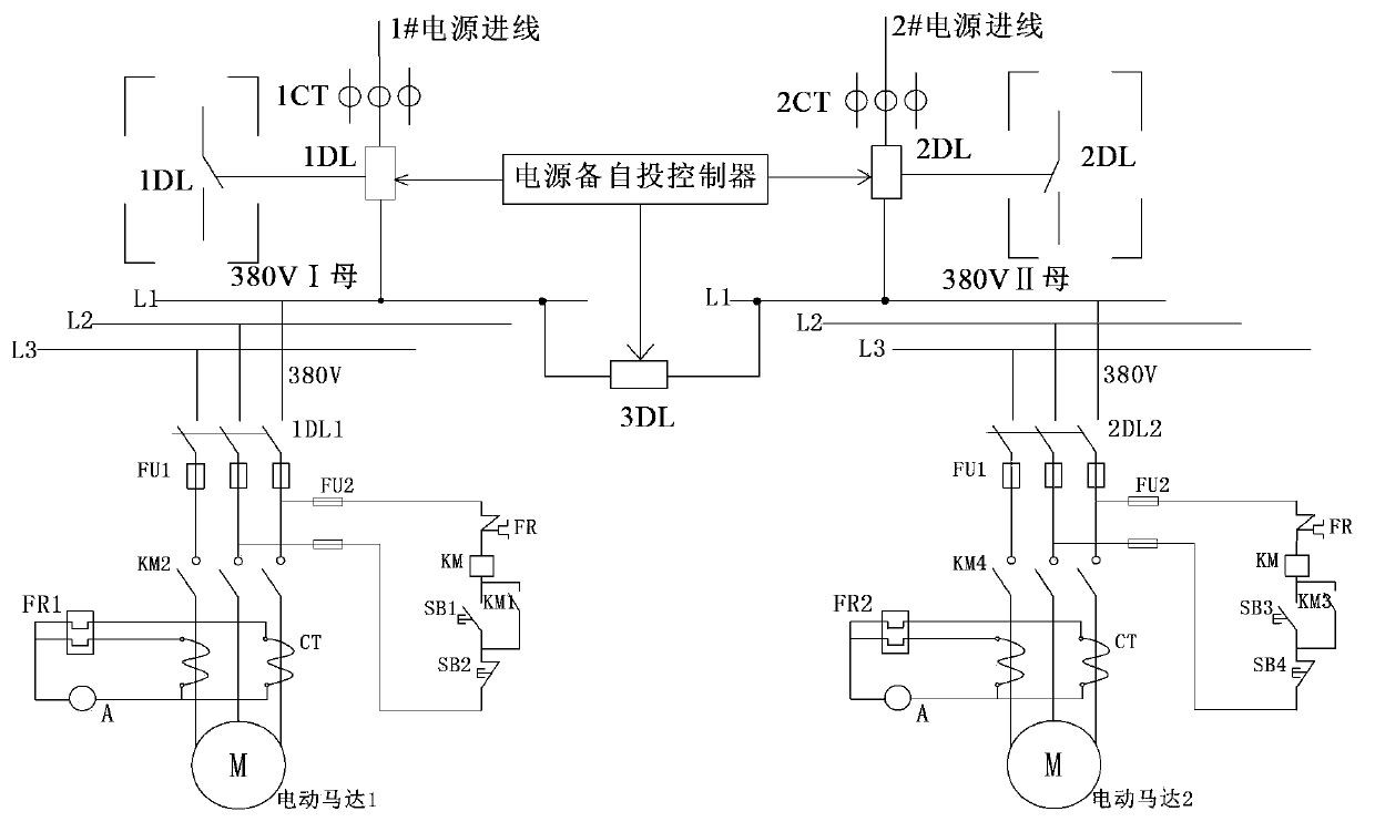
[0034] figure 1 Among them, the main circuit power supply of the motor is drawn from a certain section of the busbar in the substation, and the substation adopts a double-circuit incoming power supply and a single busbar segmented operation mode to supply external power, and the described double-circuit incoming power supply includes the first and second roads Incoming power supply, the first and second incoming power supplies are respectively connected to the corresponding first and second bus sections through the first and second incoming switches, between the first and second bus sections There is a contact switch between them, and the contact switch is controlled by the "preparation self-switching" device; when the first or second incoming power supply has a "power failure" fault, the "preparation self-switching" device jumps off the The incoming line switch corre...


PUM


Abstract

The invention belongs to the field of running control of motors and discloses a locking method for preventing a motor from being switched into a short-circuit fault. The locking method includes that by improving a motor control loop and adopting double locking logic of switch quantity and analog quantity, after a spare power source automatic switch fails to lock, the motor can be effectively prevented from being mistakenly switched into the short-circuit fault; under the circumstance that a spare power source power-losing automatic switch normally acts, the motor can run safely, reliably and continuously to meet requirements of industrial and enterprise production. The locking method is a power supply method which is safe, reliable, easy to implement and used for motor running and has a double locking function, and can be widely used in the field of running control of the motors.

Description

technical field [0001] The invention belongs to the field of substation operation control, in particular to a method for power supply and start control of a motor. Background technique [0002] With the continuous development of industrial enterprises, the reliability requirements of the power supply system are getting higher and higher. In order to improve the reliability of power supply, manufacturers generally use two power supplies that can serve as backups for each other. The two power supplies (that is, the first power supply and the second power supply) are respectively connected to an independent bus section, the industry customarily calls these two power supplies a first-stage power supply and a second-stage power supply, and for these two independent busbar sections, it is usually customary to call them a first-stage busbar and a second-stage power supply. The two-section busbar (referred to as "one section" and "second section", the same below), the two sections o...

Claims


Application Information

Patent Timeline
Patent Type & Authority Applications(China)
IPC IPC(8): H02H7/085H02J9/06
Inventor 李大伟何中炜
Owner BAOSTEEL STAINLESS STEEL
Why Eureka
Try Eureka