Exhaust pipe bending machine

A technology for bending machines and exhaust pipes, applied in metal processing equipment, feeding devices, positioning devices, etc., can solve problems such as low operation accuracy, waste of exhaust pipes, and dents in pipe fittings, so as to ensure the quality of bend pipes and increase Usability, the effect of avoiding scrapping

Inactive Publication Date: 2014-08-13
CHENGDU LINGCHUAN SPECIAL IND
View PDF6 Cites 3 Cited by
  • Summary
  • Abstract
  • Description
  • Claims
  • Application Information

AI Technical Summary

Problems solved by technology

[0003] In the process of processing the exhaust pipes of high-power transport vehicles, the pipe benders on the market are usually used to bend the exhaust pipes. However, most of the pipe benders on the market have a bending angle of 90°. When using this type of pipe bender, it cannot be formed in one time
In order to meet the processing requirements of the exhaust pipe, the staff also need to proofread the bent pipe fittings. During the proofreading process, due to the low precision of manual operation, it is easy to cause the pipe fittings to break directly, or there will be obvious cracks at the bend of the pipe fittings. Depression or cracks will lead to the scrapping of the exhaust pipe, and in the process of operation, it takes a long time, the waste of materials is serious, and the labor intensity of workers is greatly increased

Method used


Image

  • Exhaust pipe bending machine
  • Exhaust pipe bending machine
  • Exhaust pipe bending machine

Examples


Embodiment 1

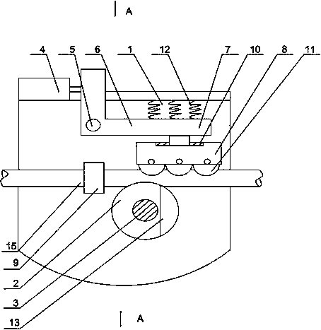
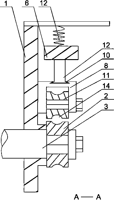
[0023] Such as Figure 1 to Figure 3 As shown, the exhaust pipe bending machine of the present invention includes a rotating disk 1, on which a pipe bend groove is installed, and on the rotating disk 1, a rotating handle 6 is hinged, and one end of the rotating handle 6 A connecting rod 7 is installed, and the other end of the rotary handle 6 is connected to the cylinder 4, and also includes a roller seat 8 and an exhaust pipe clamp 9 arranged on the rotating disk 1, and the roller seat 8 is provided with a trapezoidal groove 10, and the connecting rod The end of 7 is slidingly arranged in the trapezoidal groove 10, and a plurality of rollers 11 are installed in the roller seat 8, and guide grooves 14 matched with the groove of the elbow are opened on the roller 11, and the groove of the elbow is formed by the movable part. Composed of a fixed part, the fixed part is rotated on the rotating disk 1 through the rotating shaft 3, a protrusion is arranged on the movable part, and ...

Embodiment 2

[0025] Such as Figure 1 to Figure 2 As shown, on the basis of Embodiment 1, this embodiment further includes a plurality of torsion springs 12 , and the two ends of the torsion springs 12 are respectively connected to the rotating disk 1 and the rotating handle 6 . The two ends of the installed torsion spring 12 are respectively connected to the rotary disk 1 and the rotary handle 6. After the exhaust pipe 15 is bent, the torsion spring 12 returns to its elasticity, driving the roller seat 8 to return to its original position, so that the device can continue to perform new exhaust. Pipe 15 pipe bending process.

Embodiment 3

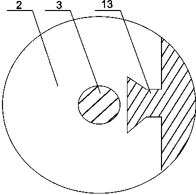
[0027] Such as image 3 As shown, this embodiment is based on Embodiment 1, the fixed part is the superior arc groove 2 , and the movable part is the inferior arc groove 13 . Because the bending angle of the exhaust pipe 15 changes little, the roller seat 8 is facing the elbow part of the exhaust pipe 15 during work, and the movable part is a inferior arc groove 13, so that the exhaust pipe 15 realizes a relatively high pressure under the impetus of the cylinder 4. Bending within a small range to ensure the strength of the bend, to avoid obvious depressions at the bend due to stress concentration, and to ensure the quality of the bend of the exhaust pipe 15 .


PUM


Abstract

The invention discloses an exhaust pipe bending machine. The exhaust pipe bending machine comprises a rotary disc, and the rotary disc is provided with a pipe bending groove and connected with a rotating handle through a hinge; one end of the rotating handle is provided with a connecting rod, and the other end of the rotating handle is connected with an air cylinder; a plurality of the wheels are mounted inside a wheel seat, and every wheel is provided with a guide groove matched with the pipe bending groove; the pipe bending groove is composed of a movable unit and a fixed unit, wherein the fixed unit is rotatably mounted on the rotary disc through a rotating shaft and provided with a slot, the movable unit is provided with a protrusion, and the protrusion and the slot are matched with each other. When the rotating handle is pressed downwards, the connecting rod can slide at a certain distance in a trapezoid groove to guarantee stress uniformity on the wheel seat; the plurality of wheels enlarge the contact area between the guide grooves and the portion to be bent of an exhaust pipe and guarantee the stress uniformity of the portion to the bent to reduce direct fracture of the exhaust pipe or cracks in the portion to be bent of the exhaust pipe, and further the rejection rate of the exhaust pipe can be reduced.

Description

technical field [0001] The invention relates to a pipe bender, in particular to an exhaust pipe bending machine. Background technique [0002] The exhaust angle of motor vehicle exhaust pipes has always been a difficult problem for professional manufacturers. According to the survey, the angle direction of the exhaust pipes of cars and light family cars is generally backward and parallel to the ground, while the angle of the exhaust pipes of high-power transport vehicles and agricultural vehicles is bent to the ground. From the perspective of environmental protection, according to the current angular direction design and mechanical design principles of motor vehicle exhaust pipes, no new angular discharge design method has been stipulated. [0003] In the process of processing the exhaust pipes of high-power transport vehicles, the pipe benders on the market are usually used to bend the exhaust pipes. However, most of the pipe benders on the market have a bending angle of 9...

Claims


Application Information

Patent Timeline
Patent Type & Authority Applications(China)
IPC IPC(8): B21D7/08B21D7/16B21D43/00
Inventor 叶维敏张军汪庭文何晓鸣杨军
Owner CHENGDU LINGCHUAN SPECIAL IND
Why Eureka
Try Eureka