A fully automatic oval tube loading machine

An oval tube, fully automatic technology, applied in coating and other directions, can solve the problems of artificial pollution, inability to achieve automatic tube loading, slow production speed, etc., to save labor costs, avoid artificial pollution, production fast effect

Active Publication Date: 2016-06-29
南通市通州区三槐机械制造有限公司
View PDF4 Cites 0 Cited by
  • Summary
  • Abstract
  • Description
  • Claims
  • Application Information

AI Technical Summary

Problems solved by technology

Since the semi-automatic hose injection machine cannot realize automatic tube loading, this injection method requires a lot of manpower and material resources, and the production speed is slow. At the same time, manual tube loading is easy to cause artificial pollution and does not meet the hygienic requirements.

Method used


Image

  • A fully automatic oval tube loading machine
  • A fully automatic oval tube loading machine
  • A fully automatic oval tube loading machine

Examples


Embodiment 1

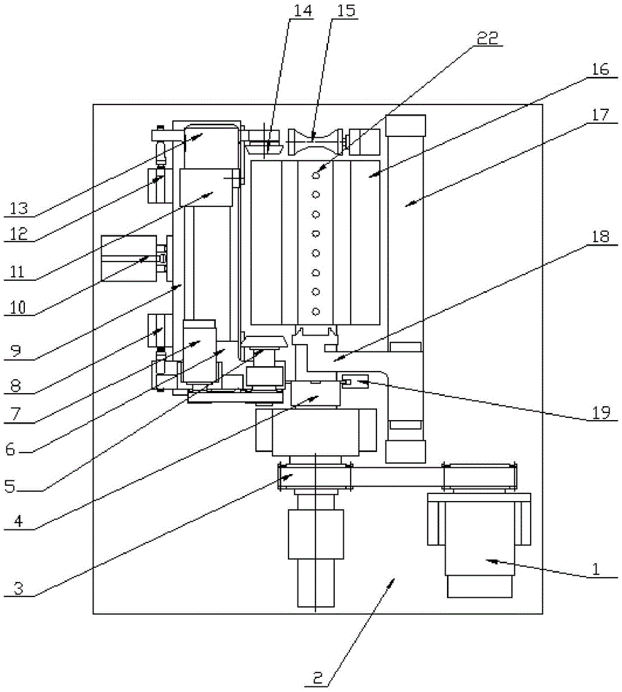
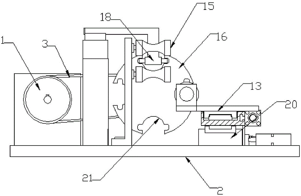
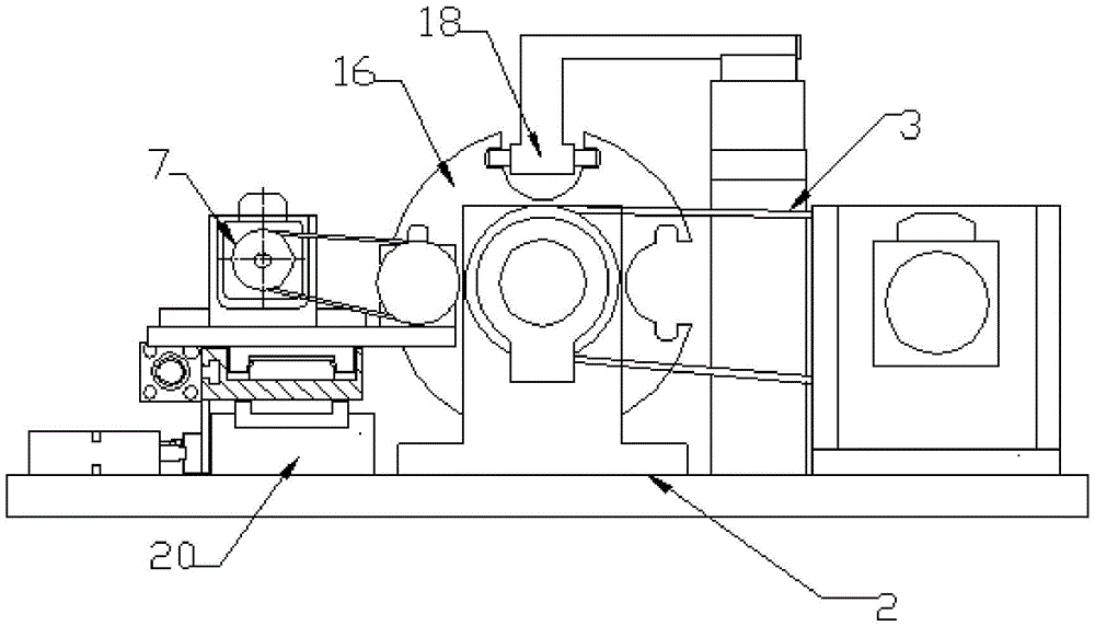
[0029] A fully automatic elliptical tube loading machine is used to realize the automatic loading function of elliptical tubes of a fully automatic shoulder injection machine, such as Figure 1-3 As shown, it includes a rack, a positioning mechanism, a pipe feeding mechanism, a calibration mechanism and an upper pipe mechanism, wherein the rack is provided with a mounting base plate 2; the positioning mechanism includes a vacuum indexing wheel 16 fixed on the mounting base plate 2 and a vacuum indexing wheel The receiving tube position, the calibration position and the upper tube position are arranged in the circumferential direction of the wheel 16, and a plurality of working grooves 21 are evenly arranged on the outer surface of the vacuum indexing wheel 16 along the circumferential direction. The working slot 21 corresponds to the receiving position, the marking position and the upper pipe position, respectively.

[0030] In this implementation, in order to facilitate the u...

Embodiment 2

[0038] All the other are identical with embodiment 1, and difference is, as Figure 4 As shown, the inner surface of the working groove 21 is provided with a positioning groove 23. The positioning groove 23 corresponds to the shape of the positioning pin 24 on the side of the upper pipe claw. When the upper pipe claw 18 pushes the hose to the forming pressure roller 15, no position deviation.

Embodiment 3

[0040] The rest is the same as that of Embodiment 2, except that an adjustment device is provided on the tube pressing device, and when the tube diameters of the hoses are different, the distance between the two forming pressure rollers can be adjusted correspondingly according to the tube diameters.

[0041] In the above-mentioned embodiment, the number of working grooves of the vacuum indexing wheel can be selected according to the actual needs of production, and the positions of the controlled position, the marked position and the upper tube position can also be set according to the actual production needs. The above-mentioned embodiment It is only one of them, but the setting principle of the present invention is not limited to this embodiment.

[0042] Beneficial effects of adopting the technical solution disclosed in the present invention: the vacuum indexing wheel is provided with a plurality of stations of the tube position, the calibration position and the upper tube p...


PUM


Abstract

The invention relates to a full-automatic elliptical tube installation machine which comprises a stander provided with a mounting bottom plate, a locating mechanism, a tube feeding mechanism, a calibration mechanism and a tube installing mechanism, wherein the locating mechanism is arranged on the mounting bottom plate, and comprises a vacuum dividing wheel, and a tube receiving position, a calibration position and a tube installing position which are arranged along the circumferential direction of the vacuum dividing wheel; the tube feeding mechanism is arranged near the tube receiving position and is used for moving a hose to be machined into a working groove; the calibration mechanism is arranged near the calibration position, and is used for shifting the hose to out from or into the working groove and calibrating the installing direction of the hose; the tube installing mechanism is arranged at the tube installing position, is used for flattening the calibrated hose after the hose is pushed outside the vacuum dividing wheel, and sheathes an elliptical mandril arranged in front of the vacuum dividing wheel. After the full-automatic elliptical tube installation machine is adopted, the elliptical hose can be automatically installed on a shoulder injection machine, the function of the full-automatic hose shoulder injection machine is improved, the production speed of elliptical hose shoulder injection is increased, and the production efficiency is greatly increased.

Description

technical field [0001] The invention relates to the field of shoulder injection machine equipment, in particular to a fully automatic elliptical pipe loading machine used for a fully automatic hose injection machine. Background technique [0002] At present, the shoulder injection of the oval hose is mainly completed on the semi-automatic hose injection machine, usually manually inserting the hose on the oval mandrel and then to the shoulder injection. Since the semi-automatic hose injection machine cannot realize automatic pipe loading, this shoulder injection method requires a lot of manpower and material resources, and the production speed is slow. SUMMARY OF THE INVENTION [0003] In order to solve the above technical problems, the purpose of the present invention is to provide a fully automatic elliptical tube loading machine, which can realize the automatic loading function of the elliptical tube of the automatic shoulder injection machine. [0004] In order to achi...

Claims


Application Information

Patent Timeline
Patent Type & Authority Patents(China)
IPC IPC(8): B29C45/17B29C45/14
CPCB29C45/14008B29C45/1418B29C45/17
Inventor 徐惠朝张艳娟
Owner 南通市通州区三槐机械制造有限公司
Why Eureka
Try Eureka