
Outlet fitting for a toilet cistern

A technology for flushing water tanks and fittings, applied in the field of drainage fittings, which can solve the problems of expensive manufacturing of drainage fittings, achieve the effects of saving materials, preventing throat noise, and improving noise

Inactive Publication Date: 2014-08-13
GEBRERIT INT
View PDF8 Cites 8 Cited by
  • Summary
  • Abstract
  • Description
  • Claims
  • Application Information

AI Technical Summary

Problems solved by technology

Although good results can be achieved with this approach in terms of noise reduction, it is desirable to minimize the noise without additional parts, since drain fittings according to EP1854926 are very expensive to manufacture

Method used


Image

  • Outlet fitting for a toilet cistern
  • Outlet fitting for a toilet cistern
  • Outlet fitting for a toilet cistern

Examples


Embodiment Construction

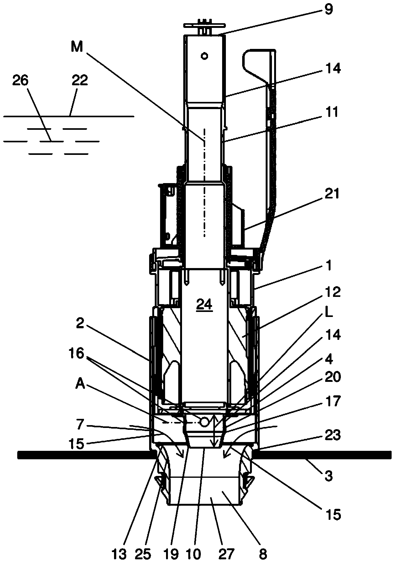
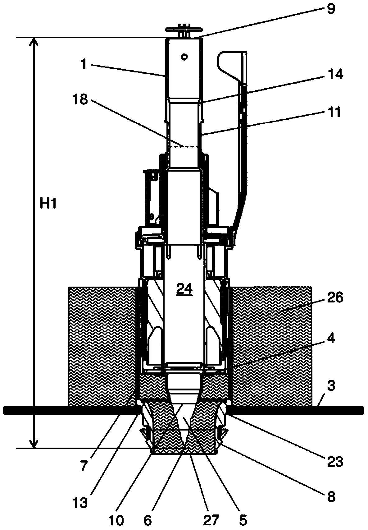
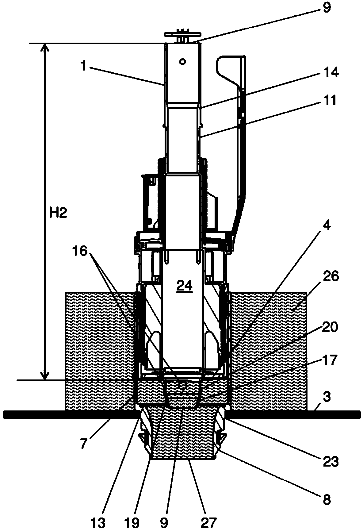
[0028] figure 1 A drain fitting 1 according to the invention is shown, which is fastened in an opening 23 of a flush tank 3 in a manner known per se. Here, only the region of the bottom of the flush tank 3 , known per se, is shown. This area is designed in a known manner such that it can hold water 26 up to water level 22 . The overflow pipe 11 has an inlet 9 at the top, which is above the water level 22 of the water 26 . The overflow pipe 11 has an outlet 10 at the bottom end. The overflow pipe 11 is arranged liftable in the housing 2 and has a buoy 12 and a closing weight 21 known per se. To bring about the flushing, the overflow pipe 11 is raised by means of an actuating device not shown here. exist figure 1 The overflow pipe 11 is shown in the raised state. In this case, the sealing element 4 is lifted from the valve seat 13 so that water 26 can pass through according to figure 2 The open valve flows out. The sealing element 4 is connected to the overflow line 11 ...


PUM


Abstract

The invention provides an outlet fitting for a toilet cistern. The fitting (1) has a valve seat (13) arranged before an outlet opening (27) when viewed in a flow direction. A sealing element (4) of an overflow pipe (11) operates together with the valve seat (13). The pipe is upwardly moved for triggering flushing. The pipe (11) includes an inlet opening (9), an outlet opening (10), and a pipe wall (14), which circulates around a middle axis (M). At least one recess (16) is arranged in the wall (14) in a lower region (17) of the overflow pipe (11).

Description

technical field [0001] The invention relates to a drain fitting for a flush tank according to the preamble of claim 1 . Background technique [0002] In generally known drain fittings of this type, flushing can be brought about by lifting the overflow pipe. The overflow pipe is usually raised by means of an actuating device, which has, for example, a button. After a flush is induced, the water stored in the flush tank passes due to gravity through the discharge outlet into the drainpipe and eventually into the toilet bowl or urinal. Flushing is interrupted by falling onto the valve seat through the overflow tube. Such a flushing process is noisy, which has various causes. In order to avoid this noise, it is proposed in the drain fitting according to CH676263A to provide a body on the underside of the valve disc, which forms a gap with the mouth edge of the discharge opening shortly before the valve is closed when the flushing is interrupted, in order to increase the Flow...

Claims


Application Information

Patent Timeline
IPC IPC(8): E03D1/34
CPCE03D1/35E03D9/14
Inventor 罗尔夫·维斯
Owner GEBRERIT INT
Learn More