Self-resetting damper of micro-vibration energy dissipation part

A self-reset, micro-vibration technology, applied in building components, earthquake-proof and other directions, can solve the problems of increasing building maintenance costs and the impact of repair costs, and achieve the effects of simple production, control of residual deformation, and reduction of residual deformation.

Active Publication Date: 2014-08-13
SOUTHEAST UNIV
View PDF6 Cites 5 Cited by
  • Summary
  • Abstract
  • Description
  • Claims
  • Application Information

AI Technical Summary

Problems solved by technology

[0003] However, under the action of medium and large earthquakes, the two plates sandwiching the damping material body will produce a relatively large parallel displacement, resulting in the cumulative residual deformation of the damper itself, which cannot return to the original state after the earthquake, thus affecting the structure after the earthquake. The repair cost has a significant impact, because with the increase of the residual deformation angle between the structural layers, the maintenance cost of the building will increase significantly, even greater than the reconstruction cost, so reducing the post-earthquake residual deformation of the damping energy-dissipating device needs to be improved one of the problems

Method used


Image

  • Self-resetting damper of micro-vibration energy dissipation part
  • Self-resetting damper of micro-vibration energy dissipation part
  • Self-resetting damper of micro-vibration energy dissipation part

Examples


Embodiment 1

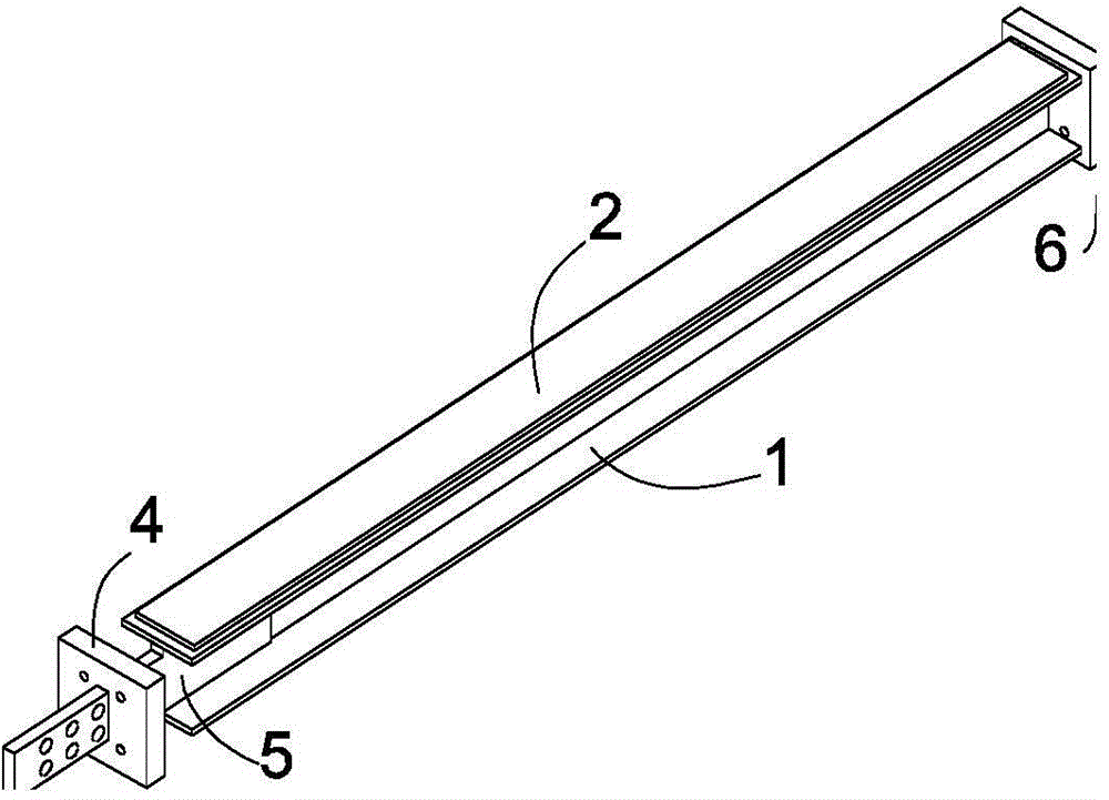
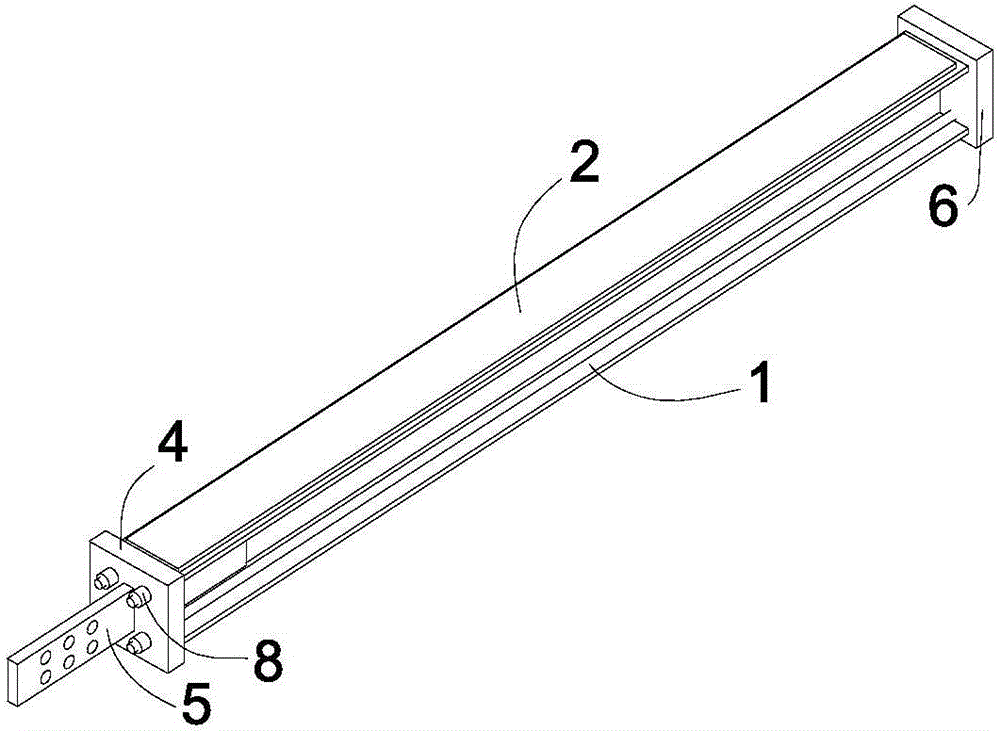
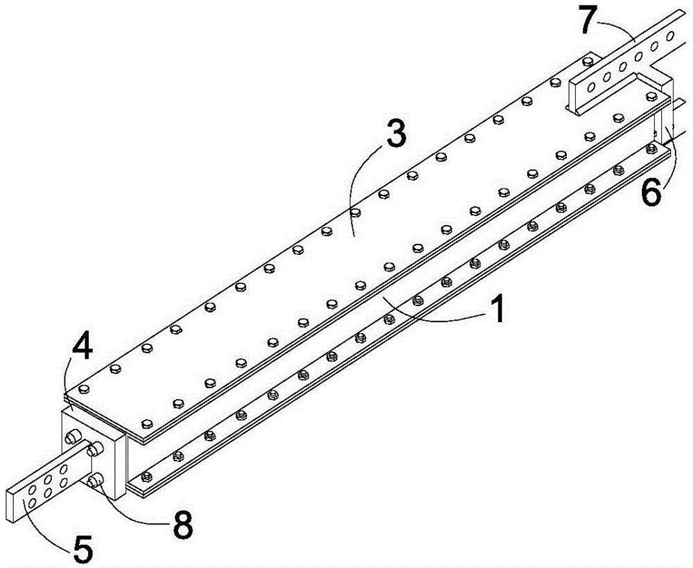
[0028] Such as Figure 1-6 As shown: the self-resetting damper of the micro-vibration energy dissipation part in this embodiment is composed of an inner restraint component 1, a damping material body 2, an outer restraint component 3, an anchor plate 4, a connecting plate 5, an anchor plate 2 6, and a connecting plate Two 7 and a tension system 8, the damping material body 2 is located between the inner constraint component 1 and the outer constraint component 3, the outer surface of the inner constraint component 1 is fixed to the damping material body 2, and the inner surface of the outer constraint component 3 is connected to the damping material The body 2 is fixed, and along the length direction of the inner restraint part 1 or the outer restraint part 3, the inner restraint part 1 is longer than the outer restraint part 3 by a certain distance at both ends, and the tension system 8 is anchored on the anchor plate 1 and the anchor plate 2 6, simultaneously press the ancho...

Embodiment 2

[0030] Such as Figure 7 As shown, the difference between this embodiment and Embodiment 1 lies in that the cross section of the inner constraint member 1 is a rectangular tube.

Embodiment 3

[0032] Such as Figure 8 As shown, the difference between the present embodiment and the second embodiment is that the damping material body 2 is divided into four pieces, which are located around the inner restraint part 1 and the outer restraint part 3 .


PUM


Abstract

The invention discloses a self-resetting damper of a micro-vibration energy dissipation part. The self-resetting damper comprises an inner restricted component, a damping material body, an outer restricted component, an anchor plate I, a connecting plate I, an anchor plate II, a connecting plate II and a tension system, wherein the inner restricted component is arranged inside the outer restricted component, and the free length of the inner restricted component is greater than that of the outer restricted component; the anchor plate I and the anchor plate II are tightly pressed at the two ends of the inner restricted component; the tension system is anchored on the anchor plate I and the anchor plate II respectively through pretension steel stranded wires or shape memory alloy or fiber bars; the connecting plate I penetrates through the anchor plate I and is fixedly connected with the inner restricted component; the connecting plate II penetrates through the anchor plate II and is fixedly connected with the outer restricted component; the damping material body is arranged between the inner restricted component and the outer restricted component. Energy dissipation is realized during wind vibration and earthquake at the same time, so that the rigidity of the damper under the effect of moderate and major earthquakes is improved, and multiple effects of residual deformation of the damper can also be effectively controlled.

Description

technical field [0001] The invention belongs to the technical field of structural engineering and relates to a novel damping energy consumption device. Background technique [0002] Damping energy-dissipating devices, such as viscoelastic dampers, are energy-dissipating and shock-absorbing components that dissipate seismic energy by sandwiching a damping material between two plates to cause shear deformation. When the two plates produce relative parallel displacement, the damping material body produces shear deformation, and the resistance force with hysteretic characteristics plays a role to absorb vibration energy. The mechanism by which the damping material body absorbs vibration energy also works when it is slightly deformed. Therefore, the damping material body can exert stable energy absorption performance under the action of micro-vibration and earthquake caused by wind or traffic vibration. [0003] However, under the action of medium and large earthquakes, the two ...

Claims


Application Information

Patent Timeline
Patent Type & Authority Applications(China)
IPC IPC(8): E04B1/98
Inventor 王春林张建东陈泉曾滨吴京
Owner SOUTHEAST UNIV
Why Eureka
Try Eureka