Suspended rotary water pressure energy converted power output device

A power output and water pressure technology, applied in the field of suspended rotary water pressure energy conversion power output device, can solve the problems of poor operability and controllability, limited use of geographical environment, unsuitable for industrial production and power generation, etc.

Inactive Publication Date: 2014-08-13
张维国
View PDF7 Cites 0 Cited by
  • Summary
  • Abstract
  • Description
  • Claims
  • Application Information

AI Technical Summary

Problems solved by technology

Although the device is simple in structure, it is not suitable for industrialized production of power generation, and the water flow must be guaranteed during the production process, which limits the geographical environment of the invention.
At the same time, during each water filling and water discharge process, the hydraulic energy generated is discontinuous, and there are disadvantages such as poor operability and controllability.

Method used


Image

  • Suspended rotary water pressure energy converted power output device
  • Suspended rotary water pressure energy converted power output device
  • Suspended rotary water pressure energy converted power output device

Examples


Embodiment 1

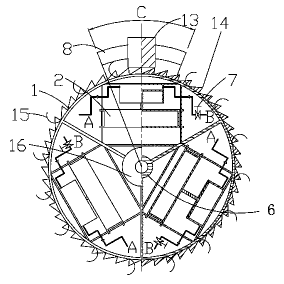
[0017] The present invention includes an energy converter 2 fixedly connected with the rotating shaft 6, a ring frame 1 concentric with the rotating shaft 6 and fixedly connected, an overturning mechanism 3, a support 4 and a hydraulic transmission mechanism. The transmission mechanism is composed of a hydraulic cylinder 19, check valves 24, 25, oil pipes 26, 27, a hydraulic oil tank 11, a high-pressure oil accumulator 12 and a hydraulic actuator 5.

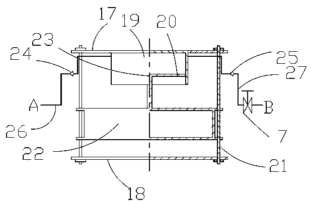
[0018] The energy converter 2 includes a buoy 22, upper and lower base plates 17, 18, a hydraulic cylinder 19 and a piston 20; the upper and lower base plates 17, 18 are connected and fixed by at least two fixing rods 21, and the hydraulic cylinder 19 is installed on the upper base plate 17; The upper end of the buoy 22 is provided with a connecting rod 23, which is connected with the piston 20 of the hydraulic cylinder 19 installed on the upper base plate 17; The oil inlet of the hydraulic cylinder 19 is equipped with a check va...

Embodiment 2

[0026] The structure of the energy converter in the second embodiment is different from that of the energy converter in the first embodiment. The energy converter 2 includes a buoy 38, upper and lower base plates 31, 32, two hydraulic cylinders 33, 34 installed on the upper and lower base plates 31, 32 and pistons 35, 36 matched with the hydraulic cylinders; the upper and lower base plates 31, 32 Connected and fixed by at least two fixed rods 37; the upper and lower ends of the buoy 38 are respectively provided with connecting rods 39, 40, which are respectively connected with the pistons 35, 36 of the two hydraulic cylinders 33, 34 installed on the upper and lower bottom plates 31, 32 facing each other The buoy 38 is movably connected with the fixed rod 37 through a linear bearing, and the buoy 38 can slide on the fixed rod 37; the oil inlet ends of the two hydraulic cylinders 33, 34 are equipped with a check valve 41, 42 respectively and are connected by an oil pipe 45 At th...

Embodiment 3

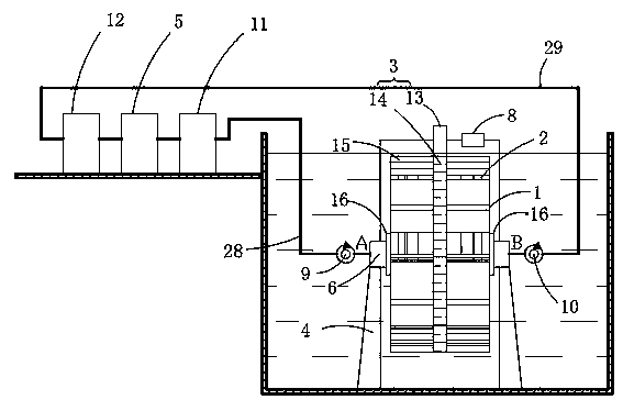
[0034] The device of the present invention can be installed in a water storage tank, and the device of the present invention includes a support, a rotating shaft, an energy converter and a hydraulic transmission mechanism, and is characterized in that: it is in an annular ring with the rotating shaft 6 installed on the support 4 as the axis At least three energy converters 2 are installed inside the frame 1 according to radial uniform distribution. The transmission mechanism is composed of a hydraulic cylinder 19, check valves 24, 25, oil pipes 26, 27, a hydraulic oil tank 11, a high-pressure oil accumulator 12 and a hydraulic actuator 5. The turning mechanism 3 is directly connected with the rotating shaft 6 and directly drives the rotating shaft. The energy converter 2 fixedly connected with the rotating shaft 6, the annular frame 1 concentric with the rotating shaft 6 and fixedly connected, the turning mechanism 3 and the support 4 are all below the water surface, and the c...


PUM


Abstract

A suspension rotary water pressure energy conversion power output device. The device comprises energy converters (2) fixed to a rotating shaft (6), a ring shape frame (1) being concentric with and fixed to the rotating shaft (6), a turnover mechanism (3), a supporting base (4) and a hydraulic transmission mechanism. At least three energy converters (2) are radially and uniformly arranged around the rotating shaft (6). The ring shape frame (1) is driven by the turnover mechanism (3) to rotate. The device is arranged in the water in a microgravity suspension state, the device is circularly and continuously rotated around the rotating shaft under smaller external force. During the rotation, the floating energy is converted to hydraulic energy by releasing a floating buoy. By multiple said devices used in combination, the hydraulic oil is pressed into a high pressure oil accumulator continuously to be used directly or for electric power generation in a hydraulic generator.

Description

technical field [0001] The invention belongs to the field of water energy conversion devices of energy conversion equipment, and in particular relates to a suspension and rotation type water pressure energy conversion power output device. Background technique [0002] Water energy is a renewable energy and a clean energy, which refers to energy resources such as kinetic energy, potential energy and pressure energy of water bodies. At present, water energy applications only use the kinetic energy and potential energy of water. Hydropower generation is a typical use of water kinetic energy and potential energy for power generation. Hydropower generation has many problems such as difficult construction, high installation cost, weak controllability, and low power generation efficiency. Water energy is a renewable and clean energy. In addition to kinetic energy and potential energy, water energy also contains huge pressure energy. Utilization of this pressure energy can greatly ...

Claims


Application Information

Patent Timeline
Patent Type & Authority Applications(China)
IPC IPC(8): F03B17/02F03B1/00F03B3/00F03B13/00
CPCF03B17/02F03B17/063F05B2260/406F03B17/025Y02E10/20
Inventor 张维国
Owner 张维国
Why Eureka
Try Eureka